Coil Winding Basics for Precision Applications

Key Technical Insights

  • Orthocyclic winding of round wire achieves fill factors above 85 % in production (theoretical limit 90.7 %); helical winding trades fill factor for pitch-controlled field uniformity along the coil axis.
  • CNC-controlled linear, flyer, and needle winding each serve distinct coil and stator architectures; method selection is driven by workpiece geometry, fill factor requirements, and production volume.
  • Reproducibility depends on tracking and stabilising every parameter that affects coil properties — wire tension, traverse timing, layer-step positioning, 0.1 µm wire tolerance, and baking profile — across the full production run.


Open PDF Version

Introduction

Electromagnetic coils are at the heart of scanning magnets, beam-steering dipoles, actuators, transformers, and sensors. While the electrical design defines the required turns, conductor cross-section, and current density, it is the winding process that determines whether those parameters are realised in practice. Fill factor, dimensional tolerances, and parasitic field components are all governed by how the wire is placed.

Winding Methods

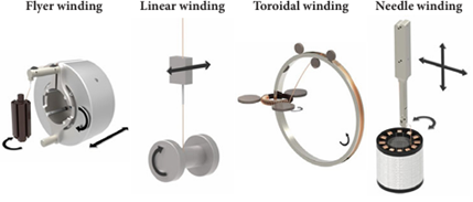
Modern coil winding relies on CNC-controlled machinery. Four methods dominate plus schemes to lower parasitic capacitance Cp.

Characteristic

Linear

Flyer

Needle

Toroidal

Low Cp

Max speed (kRPM)

30

12

2.5

2.5

10

Max fill factor

90.1 % (orthocyclic)

70% (layered)

Wire stress

Low

Medium (due to flyer arm)

High (due to needle arm)

Medium (due to needle rotation)

Automation

High

Small

Medium

Costs

Low

Medium

High

Medium

Medium

Typical applications

Bobbins, self-carrying coils, sensors

Rotor lamination stacks, outside-running motors

Internally slotted stators and correctors

Toroidal transformers

Ignition coils HV inductors Piezo drivers Resonant Converters

Linear winding

Linear winding feeds wire through a guiding nozzle while the coil body rotates on a spindle. The nozzle traverses axially, distributing wire with pitch accuracy matched to the wire diameter. Speeds can reach 30 000 turns per minute on fine wire, and the method scales by duplicating spindles — twenty or more coils wound simultaneously. This is the workhorse for bobbins, self-carrying coils, and any geometry mountable on a spindle.

Alpha Winding

Alpha Winding is linear winding that starts from the centre of the wire length rather than from one end, winding outward in both directions so that both leads exit from the same side of the coil. This is essential in applications where lead routing is constrained, e.g. galvo motors, where both connections must be accessible from one end of the assembly. Alpha winding is covered in detail in the article Galvo Coils.

Needle winding

Needle winding passes a hollow needle through stator slot channels, depositing wire directly onto the teeth. It is the only practical method for internally slotted stators and produces a finished assembly in a single operation. The wire exits at approximately 90°, which limits clean orthocyclic results to wire diameters below roughly 1 mm.

Flyer winding

Flyer winding rotates the wire source around a stationary coil body, accommodating heavy or bulky assemblies such as rotor lamination stacks. Precise placement close to the coil surface is harder than with linear winding, but orthocyclic quality is achievable by exploiting the wire's self-guiding behaviour in the grooves of the previous layer.

Toroidal winding

Toroidal winding the simultaneous rotation of the wire source and of the toroidal core create the desired winding.

Low Cp techniques’

Low Cp techniques’ primary advantage is electrical: by limiting the number of turns per section, the voltage difference between adjacent layers is kept low, which reduces inter-layer voltage stress and distributed capacitance, see Dynamical Specification.

Bank winding

Bank winding divides the winding space into narrow axial sections or "banks." Within each bank, the wire is wound in a small pyramid — a few turns wide, building up several layers before the nozzle advances to the next section. This produces a characteristic stepped cross-section that progresses axially along the bobbin.

Sectional winding

Sectional winding divides the bobbin into physically separated chambers with flanges or barriers. Each chamber is wound independently with standard layer technique.

Basket weave (honeycomb) winding.

Basket weave (honeycomb) winding. Basket weave, honeycomb, and scatter winding are different names for the same technique: successive layers are wound at a large crossing angle (approaching 90°), so that the wires in adjacent layers are never parallel over extended lengths. Typical η is 50–65 %, depending on the crossing angle — larger angles give better Cp and proximity effect reduction but worse packing. The coil is also physically larger for the same inductance, increasing leakage inductance. Basket weave is not self-guiding and requires cotton, silk, or nylon serving on the wire to maintain friction between crossed turns.

Winding Geometries

Wild (jumble) winding

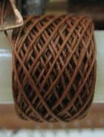
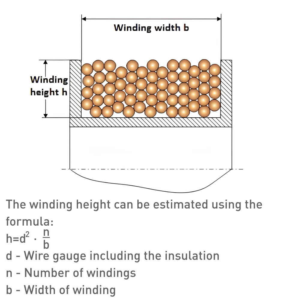
Wild (jumble) winding places turns randomly. Fill factors are limited to 73–80 % for round wire, resistance varies from coil to coil, and poorly defined conductor positions make it unsuitable where field homogeneity matters. It remains common in relay coils, contactors, and small motors where cost dominates.

Othocyclic winding

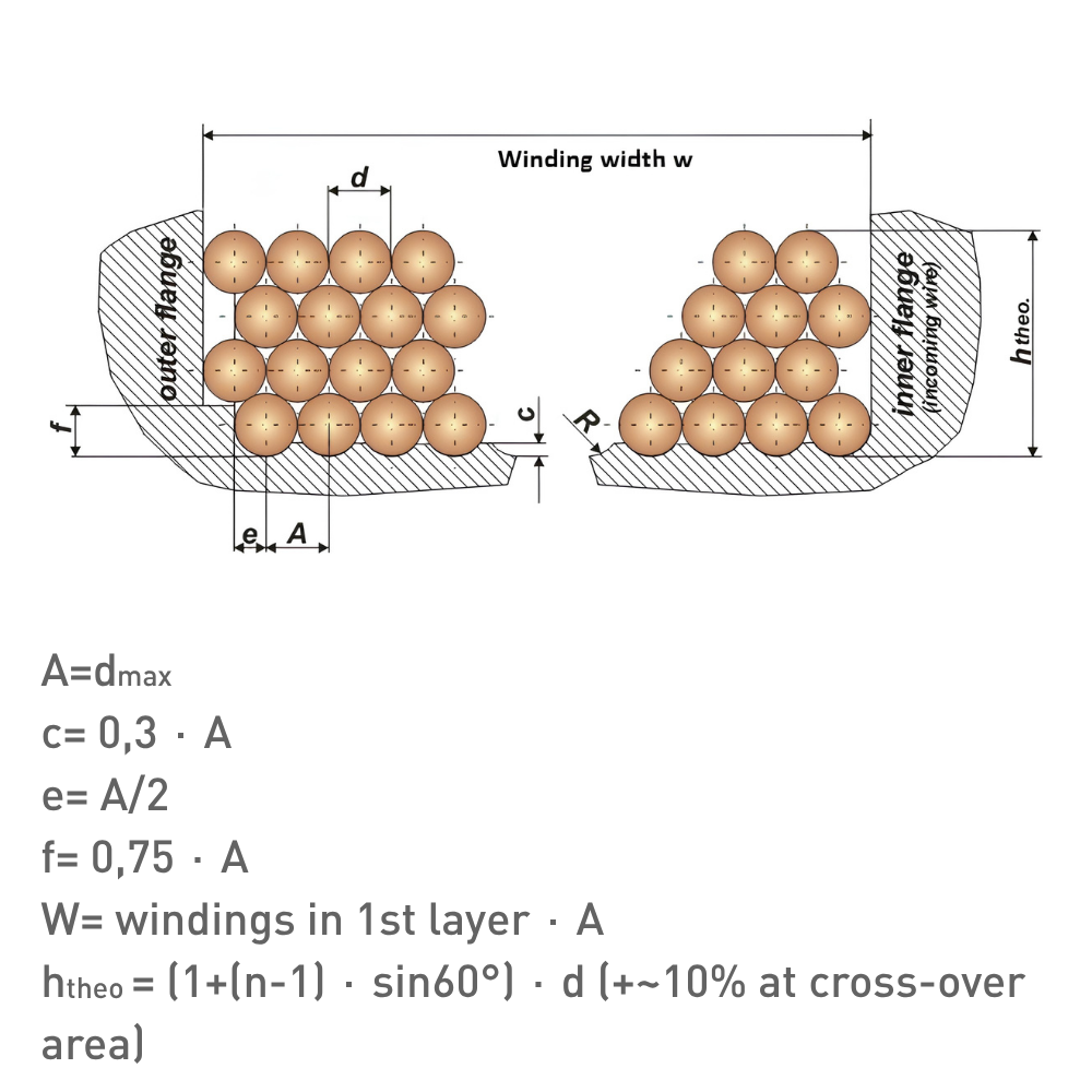
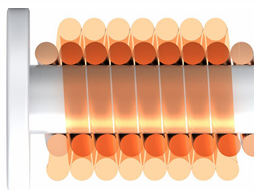
Othocyclic winding nests each turn into the groove formed by the two turns below it, producing a hexagonal close-packed cross-section for at least 300° of the circumference. Production fill factors above 85% are routine. The dense structure also improves thermal conductivity by minimising air gaps between turns. Achieving orthocyclic quality demands tight cumulative tolerances on wire diameter and winding-space width. Wire straightness matters: residual curvature from supply spools can prevent turns from seating correctly, so pre-stretching is applied to ensure consistent placement. Grooved coil bodies guarantee first-layer positioning, after which the wire's self-guiding behaviour takes over. The winding step — where the wire transitions between layers — adds 5–10 % to local winding height and should be located on the narrower side of non-circular coils to avoid interference with neighbouring components.

Helical winding

Helical winding arranges turns in a single-layer helix along the length of a cylindrical or conical former at a controlled pitch, with no layer-to-layer stacking. This geometry is used where a distributed, uniform field profile along the coil axis matters more than maximum fill factor — for example in solenoids, gradient coils, and certain RF inductors. Because there is only one layer, the winding step and crossover issues of orthocyclic winding do not arise, but pitch accuracy becomes the dominant tolerance: any variation in turn spacing translates directly into field non-uniformity.

Conductor and Coil Geometry Options

Bifilar and trifilar configurations wind two or three conductors simultaneously for balanced resistance paths or integrated sense windings. Wire diameters from 40 µm to 3 mm are routinely processed. Where field quality demands it, diameter tolerances down to 0.1 µm are achieved by specifying precision drawing dies and incoming inspection of wire batches — at these tolerances, die wear and lubrication consistency during wire drawing become controlling factors. Coil cross-sections include round, oval, trapezoidal, and pyramidal geometries. A detailed comparison of round, rectangular, and foil conductors is covered in the companion paper Wire Types for Precision Coils.

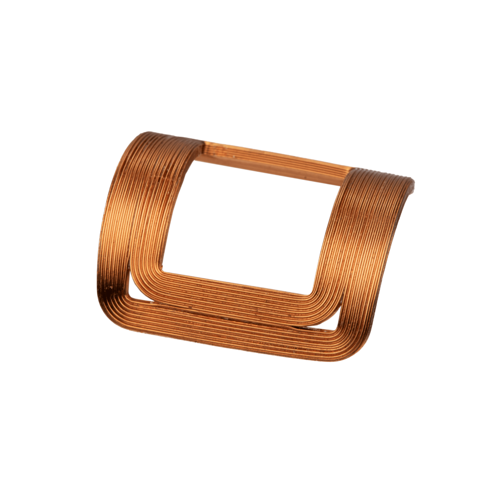
For self-carrying coils, a thermoplastic adhesive layer bonds during a controlled baking step, eliminating bobbins or potting. Proprietary baking processes maximise dimensional stability and minimise parasitic field contributions by ensuring symmetry and precision in turnovers, legs, and bending radii. Where the application requires a curved coil, the straight winding is subsequently precision-bent — a process covered in the companion paper Precision Bending of Self-Carrying Coils.

Reproducible Production

Reproducibility rests on an optimised combination of craftsmanship and automation: CNC axes handle deterministic motions (traverse pitch, spindle speed, tension control), while skilled operators manage setup, first-article validation, and process adjustments. Every step affecting coil properties is tracked and stabilised. In-house tool development ensures winding jigs and fixtures match each geometry and support transfer to downstream processes without loss of alignment.

Q&A

When is helical winding preferred over orthocyclic winding?

Helical winding is the better choice when a single-layer, distributed field profile along the coil axis is required — as in solenoids, gradient coils, or RF inductors. Orthocyclic winding maximises fill factor in a compact cross-section, but it builds up multiple layers and introduces crossover regions that can perturb the field locally. Helical winding trades fill factor for pitch-controlled field uniformity along the length of the coil.

What limits the maximum wire diameter for needle winding?

The wire exits the needle at roughly 90°, imposing a sharp bend that leaves residual curvature in the deposited turn. Above about 1 mm diameter, the stiffness of the copper makes this curvature severe enough to disrupt orthocyclic layer buildup and risk insulation damage. Linear or flyer winding is preferred for heavier conductors.

How does orthocyclic winding improve thermal performance?

In a wild winding, random air gaps between turns act as thermal insulators, creating hot spots. Orthocyclic packing minimises these gaps, providing a more continuous copper-to-copper conduction path from the inner layers to the coil surface. This allows higher sustained current densities without exceeding temperature limits.

Why are self-carrying coils preferred over potted or bobbin-wound alternatives?

Self-bonding wire eliminates external fixation components, saving volume and cost while shortening the tolerance chain. The coil remains reworkable — a failed winding can be stripped and re-wound on the same tooling. Dimensional stability under load is also improved, because the distributed adhesive bond is more uniform than localised potting or clamping.

What role does wire pre-stretching play in winding quality?

Wire from supply spools retains residual curvature and diameter variation from the drawing process. Pre-stretching (controlled elongation) straightens the wire and brings it to a more uniform cross-section before it reaches the coil body. This ensures that each turn seats predictably in its groove, which is essential for maintaining orthocyclic geometry across all layers.

Discover our custom-designed coil assemblies

We partner with our customers to engineer and manufacture high-quality coils assemblies. Through close collaboration, we tailor each solution to meet exact application requirements—ensuring reliability, performance, and seamless integration into advanced systems.

More information

Contact our expert Stefan Slot

Get expert advice on custom coil assemblies tailored to your application.