Precision Bending of Self-Carrying Coils

Key Technical Insights

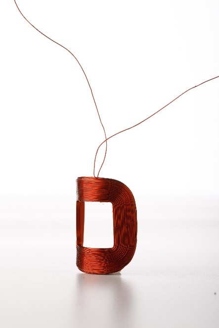
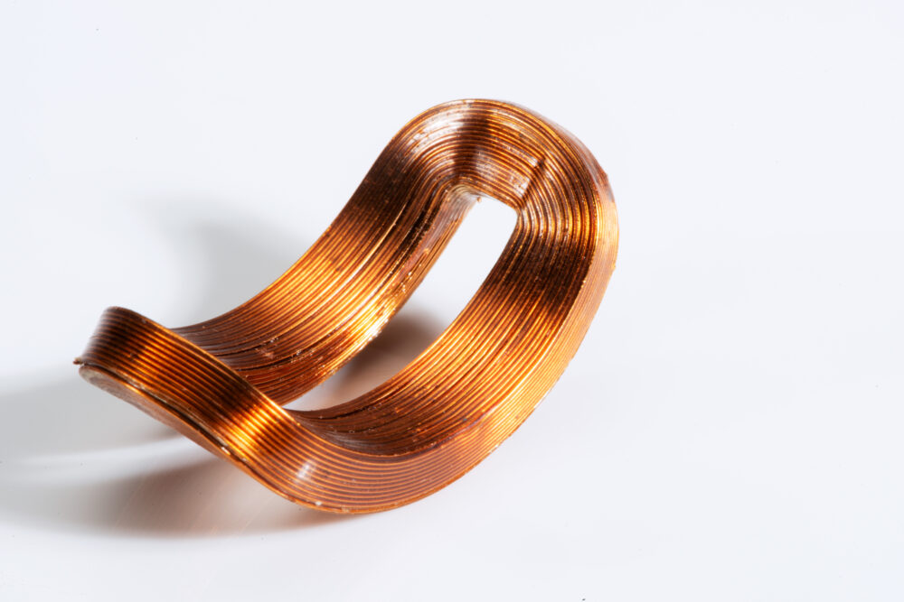
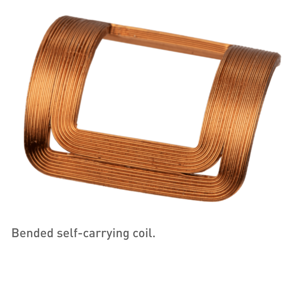
  • Combine winding repeatability with geometric freedom: self-carrying coils use thermoplastic-bonded round wire wound straight on CNC machines, then bent to the required curved geometry
  • Bending introduces coupled risks: conductor strain, loss of orthocyclic turn positions, and tight tooling tolerances bends routinely require CT scan validation and electrical surge testing
  • When tooling and process are properly engineered, precision bending is a well-established production method that delivers reproducible magnetic field quality


Open PDF Version

Introduction

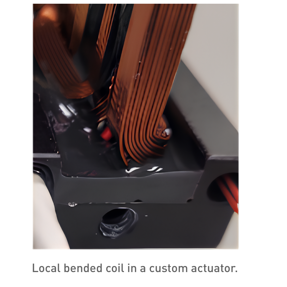
Many scanning magnets, dipoles, and custom actuators require curved current-carrying conductors that conform to the geometry around a particle beam or to improve field density. Since straight winding on modern CNC machines is fast, reproducible, and well characterised, the preferred approach is to wind a straight coil first and then form it into the desired shape. The critical challenge in this sequence is maintaining magnetic field quality — specifically, keeping parasitic field components (unwanted higher-order multipoles) within specification after bending.

Self-Carrying Coil Design

Self-carrying (self-supporting) coils are preferred in many applications because they eliminate the need for external potting frames or fixation hardware. The wire typically features a thermoplastic adhesive layer on top of the electrical insulation, which reflows and bonds during a controlled baking step. This approach saves volume and cost, shortens the tolerance chain, and keeps the coil reworkable and replaceable. The resulting structure also exhibits greater dimensional stability under mechanical and thermal loads.
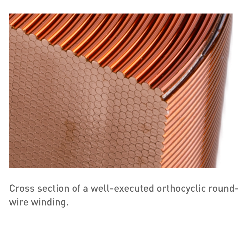
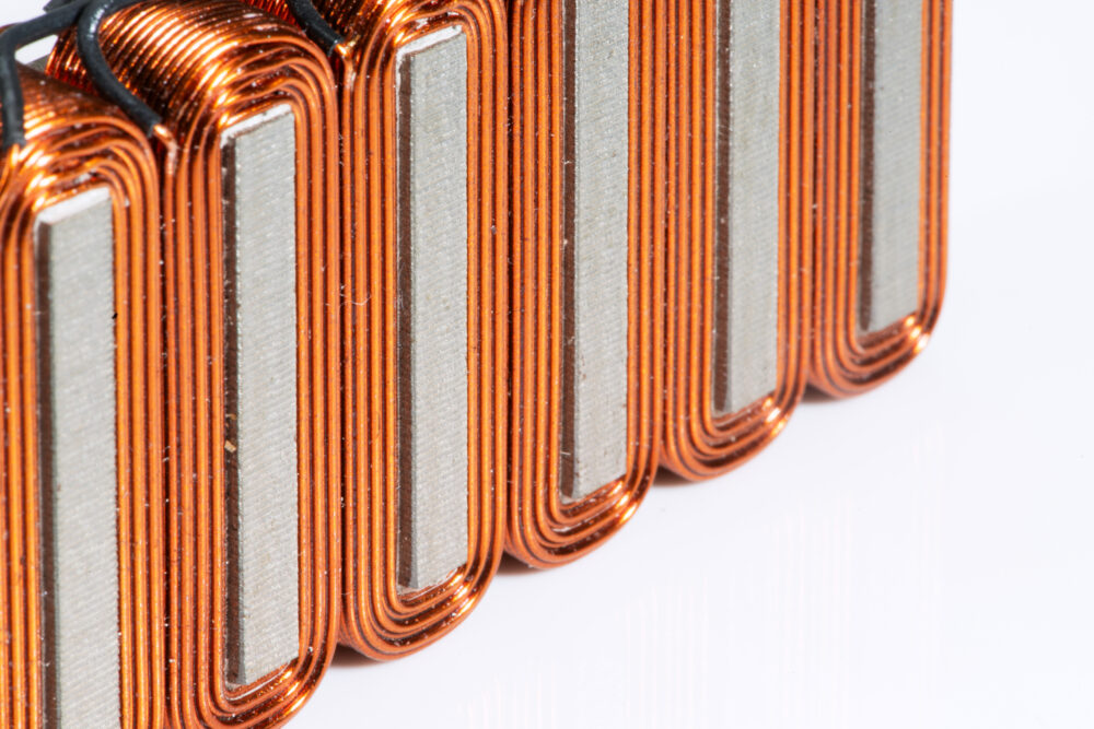
An orthocyclic winding pattern using round wire is often chosen over rectangular wire or foil. Rectangular wire requires constant operator attention, runs at lower winding speeds, and — contrary to intuition — generally yields a lower effective fill factor due to relatively more insulation and bonding material. These practical disadvantages make round wire the more economical and repeatable choice for most geometries.

Bending Challenges

Bending a finished winding pack introduces several coupled challenges that intensify with bending angle.

Strain management in conductor and insulation

Copper is ductile and therefore relatively forgiving, but inhomogeneous or excessive strain can reduce the wire cross-section locally. This adds resistance and introduces parasitic field components that degrade magnet performance. The insulation must likewise remain intact; micro-cracking can compromise dielectric strength.

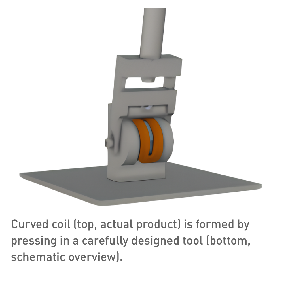
Bending tool design and tolerances

The tool must deliver the final geometry within specification while accommodating normal variation in wire diameter and winding-pack dimensions. Because baking temperatures are too low to soften either the copper or the electrical insulation, the tool cannot rely on thermal compliance and must control all forming mechanics precisely — including support of the inner and outer radii and distributed clamping to prevent localised stress concentrations.

Preservation of winding geometry

During bending, the winding pack behaves as a laminated beam: individual turns want to slide relative to one another. If this motion is not prevented or pre-compensated during the winding step, turns can shift out of their orthocyclic positions, degrading the fill factor and distorting the field pattern. In severe cases, displaced wires can damage adjacent insulation and create turn-to-turn short circuits.

Jig-to-tool transfer

The winding jig must be designed so that the coil can be transferred to the bending tool without loss of alignment or introduction of handling damage. This requires compatible datums and a transfer sequence that maintains support of the winding pack throughout.

Bending risk and verification

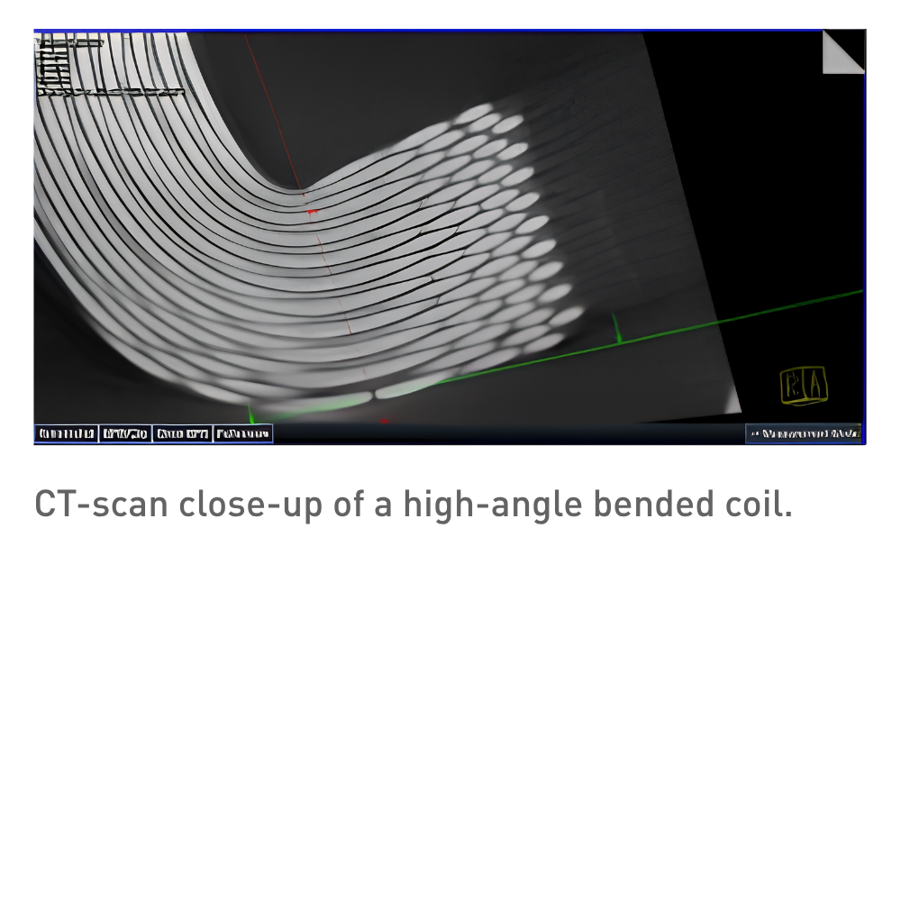
At high bending angles the risk of wire dislocation rises significantly. Process validation by CT scan is standard practice in these cases, providing a non-destructive view of turn positions and potential voids. An electrical surge test can supplement the CT data by detecting localised wire thinning that would alter resistance and field quality.

Summary

Curved current-carrying conductors are essential in particle-beam optics, specialised actuators, and a range of other applications. Straight winding followed by precision bending combines the speed and repeatability of CNC winding with the geometric freedom these applications demand.

The bending step, however, must be carefully engineered: tooling must control strain distribution and preserve winding geometry, while validated through CT scanning and electrical testing to confirm that magnetic field quality is maintained. These processes and craftmanship are well established in modern coil production, and when properly executed they deliver reproducible results within tight tolerances.

Why not wind directly on a curved mandrel instead of bending afterwards?

Straight winding on CNC machines is significantly faster, more reproducible, and easier to qualify. Curved-mandrel winding introduces variable tension, uneven layer buildup, and operator-dependent quality. Bending a straight coil separates the two challenges — winding quality and final geometry — so each can be optimised independently.

Why does orthocyclic round wire outperform rectangular wire in fill factor?

Rectangular wire theoretically packs more tightly, but in practice it requires precise orientation control on every turn. Any twist or misalignment wastes more space than the round-wire gap it was meant to eliminate. Orthocyclic round-wire winding is self-aligning — each turn nests into the valley of the layer below — so achievable fill factors are consistently higher in production.

What exactly are "parasitic field components" and why do they matter?

They are unwanted higher-order multipole contributions to the magnetic field (sextupole, octupole, etc.) caused by deviations in conductor position or cross-section from the ideal design. In beam optics, even small parasitic components can defocus or steer the beam, so they are tightly specified.

Why can't the baking step compensate for bending-induced distortion?

The baking temperature is chosen to reflow the thermoplastic adhesive, which softens well below the point where copper or polyimide insulation would anneal or deform. The coil is therefore mechanically rigid during bending — it cannot be "reshaped" thermally after forming, which is why the bending tool must get the geometry right in a single controlled step.

How does CT scanning validate the bend?

CT provides a full 3D density map of the winding pack, revealing turn positions, voids, insulation gaps, and any displaced wires — all non-destructively. It confirms that the orthocyclic geometry survived the bend and that no turns have shifted enough to risk shorts or field degradation. Surge testing complements this by electrically detecting localised wire thinning that CT resolution might miss.

Discover our custom-designed coil assemblies

We partner with our customers to engineer and manufacture high-quality coils assemblies. Through close collaboration, we tailor each solution to meet exact application requirements—ensuring reliability, performance, and seamless integration into advanced systems.

More information


Contact our expert Stefan Slot

Get expert advice on custom coil assemblies tailored to your application.