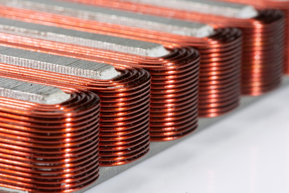
Coil Window Geometry - Variable Turns per Layer

Key Technical Insights

  • Advanced coil geometries are achieved by varying the number of turns per layer during winding, enabling coils that conform to volume constraints or produce shaped magnetic fields.
  • Orthocyclic winding is still possible in almost all cases, preserving much of the high-speed and self-guiding behavior while tapering the winding pack.
  • Variable turns per layer disrupts self-guiding at the layer edges, making CNC programming and tension control at these transition points critical to winding quality.
  • Window shaping together with coil bore shaping and post-winding bending determine the final coil geometry.


Open PDF Version

Introduction

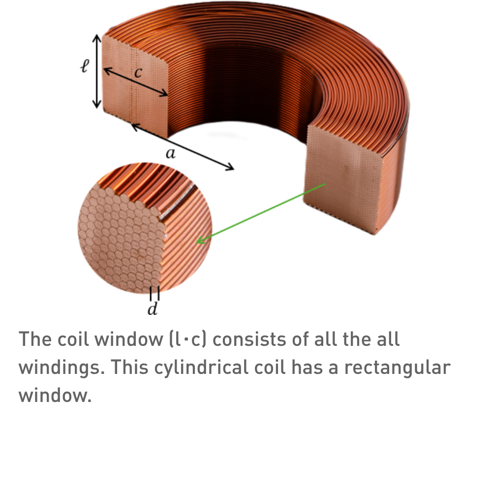
Standard orthocyclic winding fills a rectangular winding window: every layer has the same number of turns, and the coil window is a simple rectangle. Many applications, however, require coils that do not fit a rectangular envelope — because the available space is tapered, because the magnetic field must be shaped by varying conductor density, or because the coil must conform to a curved pole piece or assembly interface. These non-rectangular windows are produced by varying the number of turns per layer during the winding process. No post-winding machining or forming is involved: the geometry is built turn by turn on the CNC winding machine. This paper covers the principal window types, the winding challenges they introduce, and the relationship between to magnetic field quality. Note that we consistency talk about ‘windows’, since ‘cross-section’ can be ambiguous.

Window Types

Non-rectangular window profiles are used to match complex assembly envelopes or to combine different field contributions within a single winding. Here is a list of common types, although any shape or hybrid built out of varying turns is possible. Window shapes can be symmetric or asymmetric (one edge remains aligned while the other varies). Asymmetric winsdows are more common because they allow one reference surface to remain flat for mounting or alignment.

Taper

A tapered window removes one or more turns per layer progressively, creating a linear taper from a wide inner layer to a narrow outer layer (or vice versa). This geometry conforms to wedge-shaped or conical winding spaces — for example, the gap between tapered pole pieces in a focusing magnet, or the annular space in a conical actuator.

Stepped

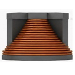
A pyramidal cross-section tapers in both the axial and radial directions, producing a peaked profile. Successive layers are both shorter (fewer turns) and offset, building toward an apex. This geometry is used when the coil must fit into a conical cavity or when the field profile requires maximum conductor density at the centre tapering to minimum at the periphery.

Wavy / Toothed

Alternating turns for each layer leads to a wavy or toothed surface. In semi-orthocyclic winding, every other layer has one turn fewer, but this still approximates a rectangular window.

Winding Challenges

Varying turns per layer introduces challenges that increase with the complexity of the cross-section.

Edge self-guiding

In a standard orthocyclic winding, every turn is flanked by neighbouring turns that constrain its position laterally. At the edge of a shortened layer, the outermost turn has no neighbour on one side. It is supported only by the groove in the layer below, which provides radial location but no lateral constraint. This unguided edge turn is the most likely to shift during subsequent winding or baking, and its position directly affects field quality at the coil boundary.

CNC crossover programming

Each layer with a different turn count requires its own traverse program — the nozzle must reverse at a different axial position. For complex windows with many distinct layer lengths, the CNC programming effort increases significantly. The crossover (winding step) position must also be managed at each layer boundary to avoid stacking crossovers on top of each other, which would create a local height buildup.

Tension management at transitions

When the nozzle reverses at a shortened layer edge, the wire must transition from the last turn of the current layer to the first turn of the next layer over a shorter distance. This changes the local bending radius and wire path, potentially affecting tension and insulation stress. Dynamic tension adjustment at these transition points is essential to prevent insulation damage (see Wire Insulation).

Fill factor at the edge

The edge region of a non-rectangular window has inherently lower fill factor than the full-width region. Edge turns that are not fully constrained may seat slightly less precisely, and the partial layers do not benefit from the same degree of self-guiding interlocking. For applications where fill factor is critical throughout the window, this must be accounted for in the design.

Interaction with Magnetic Field Quality

The magnetic field produced by a coil is determined by the exact position of every turn. In a rectangular orthocyclic window, turn positions are highly deterministic — each turn is constrained by its neighbours and by the layer below. Non-rectangular windows introduce controlled asymmetry: the field contribution of the tapered region differs from that of the full-width region, and the edge turns are positioned with slightly less certainty. For applications where the window shaping is deliberate, e.g. matching a pole piece, or shaping a fringe field, this is the intended effect. The coil designer specifies the window to produce the required field distribution, and the winding process must reproduce that window within tolerance. For applications where the window is driven by space constraints rather than field shaping, the magnetic consequences of the taper must still be evaluated. Parasitic field components arising from the non-rectangular geometry should be calculated and verified against specification (see Functional Specifications for Precision Coils).

Relationship to Other Geometry Processes

Window geometry is a winding-time decision — the shape is built turn by turn. It is distinct from three other geometry processes:

Coil bore shape determines the top-view shape of the coil. The outer shape follows the bore, since the outer layers are built on top of the inner layers, although spacers can be used to change the shape.

Precision bending forms a straight-wound coil into a curved path after winding. A coil with a non-rectangular window can be subsequently bent, combining both geometry techniques. The bending process must account for the non-uniform window when designing the bending tool (see Precision Bending of Self-Carrying Coils).

Epoxy casting encapsulates the finished coil — regardless of its window — in a protective shell. Complex windows may require more elaborate casting moulds, but the casting process itself is independent of the winding geometry (see Epoxy Casting).

Coil assemblies may combine multiple coils with different windows into a single functional unit. The window of each individual coil must be designed to fit the assembly envelope and produce its portion of the combined magnetic field (see Coil Assemblies).

Q&A

How much fill factor is lost in the tapered region?

The loss depends on the taper angle and wire diameter. For semi-orthocyclic winding, the loss is small — each shortened layer omits one turn out of many, and the remaining turns maintain full orthocyclic packing. For steep trapezoidal or pyramidal tapers, the edge effects become more significant, and fill factor in the tapered region can be 5–10 % lower than in the full-width region. The overall coil fill factor is a weighted average.


Can variable turns per layer be combined with bifilar or trifilar winding?

Yes, but the complexity compounds. Each shortened layer must accommodate the multi-strand bundle, and the edge self-guiding issues affect all strands simultaneously. The CNC programming must account for the bundle geometry at every transition point. In practice, this combination is feasible for semi-orthocyclic and simple trapezoidal profiles but rarely attempted for pyramidal or complex stepped geometries.

How is the cross-section verified after winding?

For standard production, dimensional measurement of the wound coil (height, width, profile) at multiple points confirms the window. For precision applications, particularly where the taper directly affects magnetic field quality, CT scanning provides a non-destructive view of individual turn positions throughout the window, verifying that the programmed geometry was achieved (see Qualification Testing).

Does a non-rectangular window affect bending?

Yes. The bending tool must accommodate the varying window, a tapered coil bends differently from a rectangular one because the neutral axis shifts across the taper. The inner and outer fibre strains differ from the rectangular case, and the tool must be designed accordingly. This is a solvable engineering problem but requires the bending tool design to account for the specific window geometry.

Discover our custom-designed coil assemblies

We partner with our customers to engineer and manufacture high-quality coils assemblies. Through close collaboration, we tailor each solution to meet exact application requirements—ensuring reliability, performance, and seamless integration into advanced systems.

More information

Contact our expert Stefan Slot

Get expert advice on custom coil assemblies tailored to your application.