Is the power supply manufacture do the safely analysis
No, the safety analyses must be done on the end product.

Optimizing human safety and reducing cost
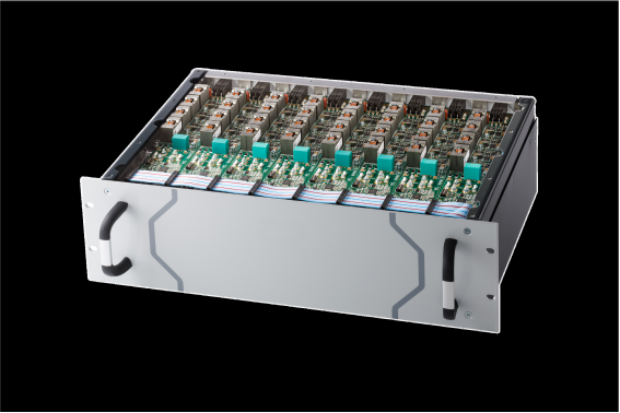
Power supplies can power hazardous systems, like e.g. a high-power LASER. These LASERS can cause Instantaneous and irreversible injury, like permanent eye damage or blindness in a fraction of a second. There is no "second chance." An interlock is often the only thing standing between normal operation and a life-changing injury.
A safety interlock is a mechanism that brings a hazardous system into a safe state. In this state, the power supply does not produce any power anymore. The interlock can be triggered by several evets
There 2 mostly used standards
The ISO standards used Performance levels (PLx), while the IEC standard used Safety Integrity Level (SILx). Altrough there are small differences between the PLx and SILx levels, the two can be mapped on each other
PL | SIL |
|---|---|
a | — |
b | 1 |
c | 1 |
d | 2 |
e | 3 |
There is also a SIL4 level, but this one is hardly used.
In general, a higher SIL or PLe level is required if the system that is power by the power supply is more dangerous
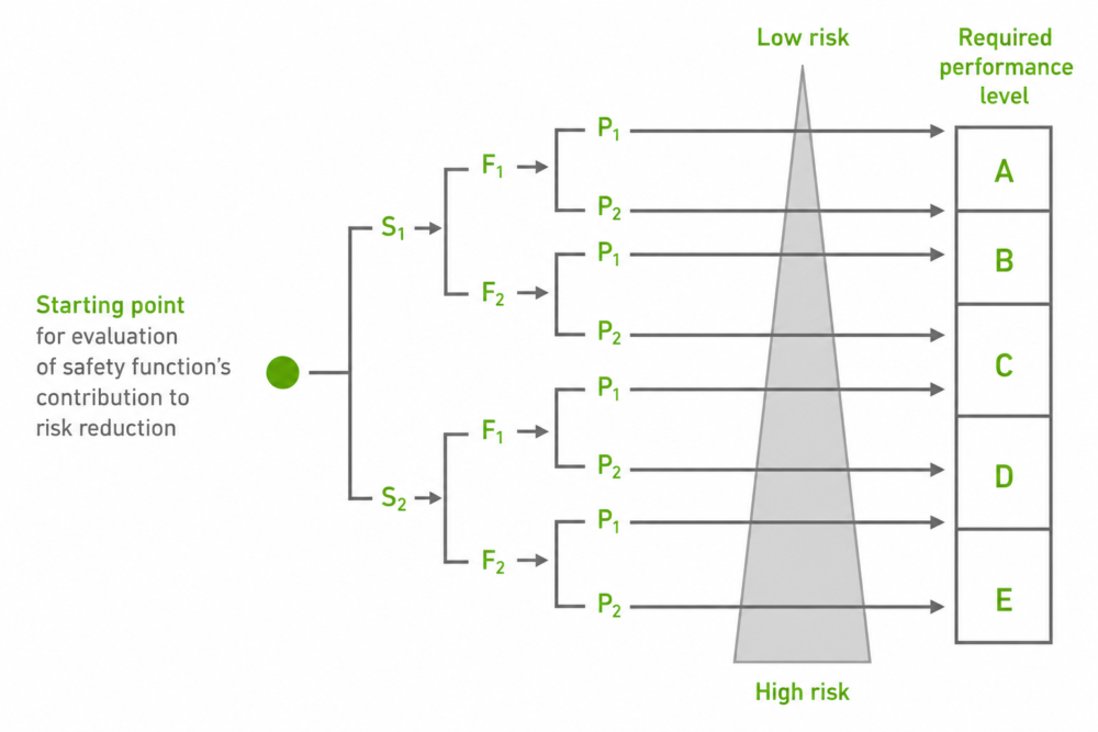
To determine the required SIL of PL level, a risk analysis need to be performed. Below the risk analysis for the ISO 13849-1 is shown. The risk assessment for the IEC 62061 is similar.
3 important questions must be answered to determine the performance lever S: severity of injury
Example: The LACS-76000 (SFC power supply: Fast current driver system) is used to power up a 2kW laser.
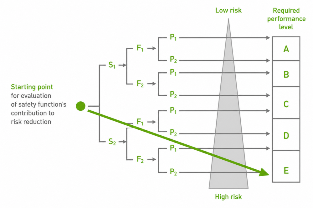
Severity op injury: These kind of lasers can cause blindness (or even worse), so the severity is S2 Frequency: Most laser systems are used very frequently, so F2 Possibility of avoiding hazard or limiting harm: Laser light is traveling with the speed of light, so avoiding is hardly possible, so P2 The outcome of the risk analysis is a PLe system
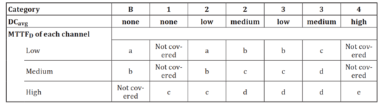
If the performance level is determined, the categories, MTTFd and DCavg can be derived Categories: This is the type of system that is chosen: e.g. a system with 1 interlock channel or with 2 interlock channels, with or without diagnostics MTTFd: Mean time to dangerous failure. A dangerous failure is a failure that can lead to un unsafe situation DCavg: average diagnostic coverage. This give the number of failures that are detected in the system.
A simplified relationship between these parameters is giver below:
Example: The outcome of the risk analysis is PLc. Now there are the following choses:
In general, if the system is very reliable (so high MTTFd) the DCavg or the category can be lower. It is depending on the design which options is the best option. If e.g. the safety system can be built with a few highly reliable cost-effective components, then the first option can be the best. But if these components are less reliable or come with a very high price, it might be better to build in diagnostics to detect the failure and go for a higher category system
Of course, using a system with a higher PL level is always allowed
A brief simplified summery can be found below
Category B: Components are used withing there specification. There is no diagnostic coverage, and a single failure of the system can lead to a hazardous situation. Single safety channel
Category 1: Well-tried components for safety applications There is no diagnostic coverage, and a single failure of the system can lead to a hazardous situation. Single safety channel
Category 2: Well-tried components for safety applications There is diagnostic coverage and failures might be detected. A single failure of the system can lead to a hazardous situation. Single safety channel
Category 3: Well-tried components for safety applications There is diagnostic coverage and failures might be detected. A single failure of the system does not lead to a hazardous situation. Double safety channels
Category 3: Well-tried components for safety applications There is diagnostic coverage and most failures are detected. A single failure of the system does not lead to a hazardous situation and a accumulation of undetected failts will nor lead to a loss of the safety function. Double safety channels
There are many ways to implement a safety circuit. The most common is to use contactors in the mains lines
If the E-stop button is pressed, the contacts inside the safety relay are opened and contactors 1 and 2 are deactivated and the mains in disconnected from the power supply. If the E-stop button is released again, and the reset button is pressed, the system is activated again
What happens at a single fault: Lets assume contactor 2 is defect.
If the E-stop button is pressed, the contacts inside the safety relay are opened and contactors 1 is deactivated. Contactor 2 is defect, but still a safe state is reached because contactor 1 is still functional. If the E-stop button is released again, and the reset button is pressed, the system is not restarted because the auxiliary contact of contact 2 is still open. So, the fault is detected. The system can now only resume operation is contactor 2 is repaired
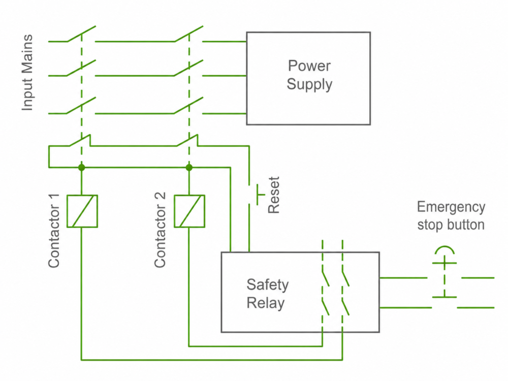
There are some disadvantages to this system
SFC developed a technique where contactors are omitted.
The contactors are not used anymore but are now in an electronic form integrated into the power supply.
The overall function is still the same.
If there is a single fault, the power supply will not close it internal contacts in series with the reset button. So, a single fault is not causing an unsafe situation, and a fault is detected
For simple systems, also the safety relay can be omitted
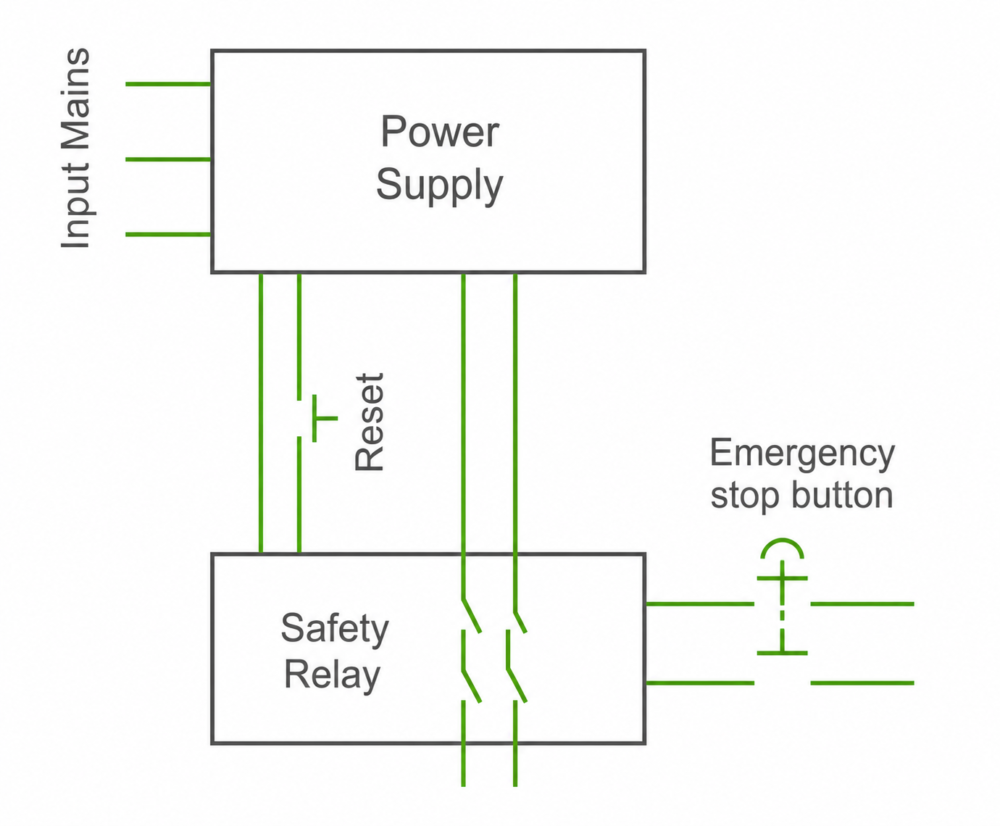
Since the power supply has a build in cross detection system, it can not only detect internal faults, but also external faults. If one of the contacts of the E-stop button fails. The power supply will detect an inconsistency between the 2 interlock signals and will be latched shut down. The only way to restart the system is a complete power cycle of the system.
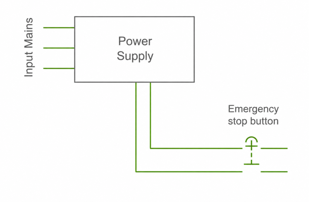
Advantages SFC interlock implementation
No, the safety analyses must be done on the end product.
No, only those that can lead to a loss of safety functionality. Components that have nothing to do with safety or components that lead failure of the power supply (failure of the power supply = safe state) are not dangerous failures. In fact, most components in the power supply are not critical for the safety circuit .
Not necessarily. For example, if the end user uses a E-stop button which only one contact, the category of the system directly goes from category 3 to category 2. Which results in maximal PLd. But since it will be now very hard to detect a single fault, probably the performance level drops to PLc or even wors. So it is very important to
This is often confused.
Lifetime:The lifetime of a power supply is normally the normal time that a power supply can be used. This can be e.g. 10 year. After these 10 years of use, the change that the power supply fault increases
MTBF: This is the mean time between failure during the normal lifetime of the product. Example: a power supply has a lifetime of 10 years (87.600 hours) and an MTBF of 3.000.000 hours. This would mean that if there are 3.000.000 units in the filed that have a lifetime of 10years or less, 1 unit per hour will fail. Or to put it differently: during the first 10 year, a power supply has a failure change of 87.600/3.000.000 = 2,92%. This results in a annual failure rate of 0,292%.
MTTFd: This is the failure rate of the safety channels. So only the parts that are safety critical are in this number. The number of parts that are safety critical are normally reduced to a minimum and are highly reliable. Therefor the MTTFd is much higher that the MTBF since in the MTBF all parts are counted. The MTTFd of a SFC power supply is typical between 650 and 5000year (5.700.000 to 43.800.000 hours). With an expected lifetime of 10 years, the expected failure rate of one channel is between 0,02 and 0,15%. And since more than 99% of the dangerous faults are detected and reported, the change that both channels fail is almost zero
Yes and no.
If you look at the schematics, it might seem easy and it might actually be. But there is more to it. Documentation of the whole design process with all the analyses are required. Single fault test must be performed. The MTTFd and DCavg must be calculated. But also other things like additional (Harder) EMC test must be preformed. Common cause failures need to be analysed: What happens if the same component is used in both safety channels. If one fails due to e.g. an external magnetic field, it is likely that the other also fails. So, two different components would be better in this case. Etc.