Net distortion in semicon FAB’s

Optimizing net stability and lowering harmonics for high power applications

Key Technical Insights

  • Growing semiconductor FABs and long cables increase harmonic distortion, risking costly production standstills and violating IEEE 519 grid limits at the Point of Common Coupling.

  • Traditional thyristor power supplies are cheap and robust but triple the ideal input current, requiring excessively thick cables and bulky line reactors to lower harmonics.

  • A single-stage diode rectifier with a buck converter significantly reduces distortion, keeping voltage harmonics just under the 8% limit even at 200 meters.

  • Low-pressure manufacturing environments lower breakdown voltages, making output voltage balancing against earth critical to prevent electrical arcing.


Open PDF Version

Introduction

Modern semiconductor FAB’s are getting bigger. With that, the power infrastructure getting more complex and the distance between the central mains transformer and the semicon manufacturing equipment increases. Due to the increased cable lengths, the harmonic distortion of the grid increases if no preventive actions are taken. This can influence equipment and can cause instabilities on the grid.

In the letter, the problem is explained, and solutions are presented.

IEEE 519

IEEE 519 is the standard titled "Recommended Practice and Requirements for Harmonic Control in Electric Power Systems." It establishes limits for electrical noise (harmonics) to ensure that power quality remains stable for everyone connected to the grid.

PCC (Point of Common Coupling)

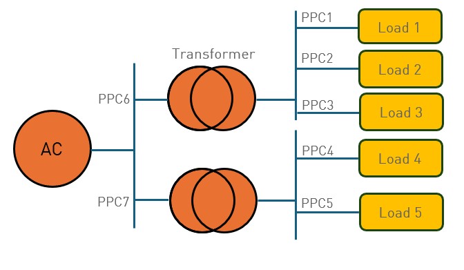
This is the most critical concept in IEEE 519. The limits are not measured inside the building at individual machines, but at the PCC—the point where the facility connects to the utility’s network.

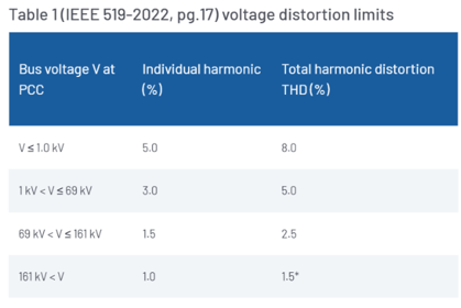
Lets assume that on PPC 1 to 5 the mains voltage is 480Vac (so below 1kV) and on PPC 6 and 7 the voltage is 10kV (so below 69kV), then on PPC 1 to 5 the total voltage harmonic distortion can be 8%, and the individual harmonic 5%.

Long cables

If a load current contains harmonics, so the input current of the load is not a perfect sine wave, it causes also voltage harmonics since the mains cable and the mains transformer have impedance.

When does this become a problem:

  • When the mains cable is long
  • When the transformer has much impedance
  • When the currents become higher

So, in either of these 3 cases, the voltage harmonics can become too high. And if they do, it can mean that other equipment might not function properly. In a semicon FAB, a single disturbance can lead to high cost: e.g. a waver can cost up to $50.000, and a FAB-line standstill can cost up to $8.500 per minute.

There are 2 ways to avoid these problems:

  • Have no Points of Common Coupling with other loads. This means that other loads, that might be close to each other, need their own mains cables. Knowing that these mains cables can be up to 200meters long, this can be costly
  • Improve the power quality of the load.

Thyristor solutions

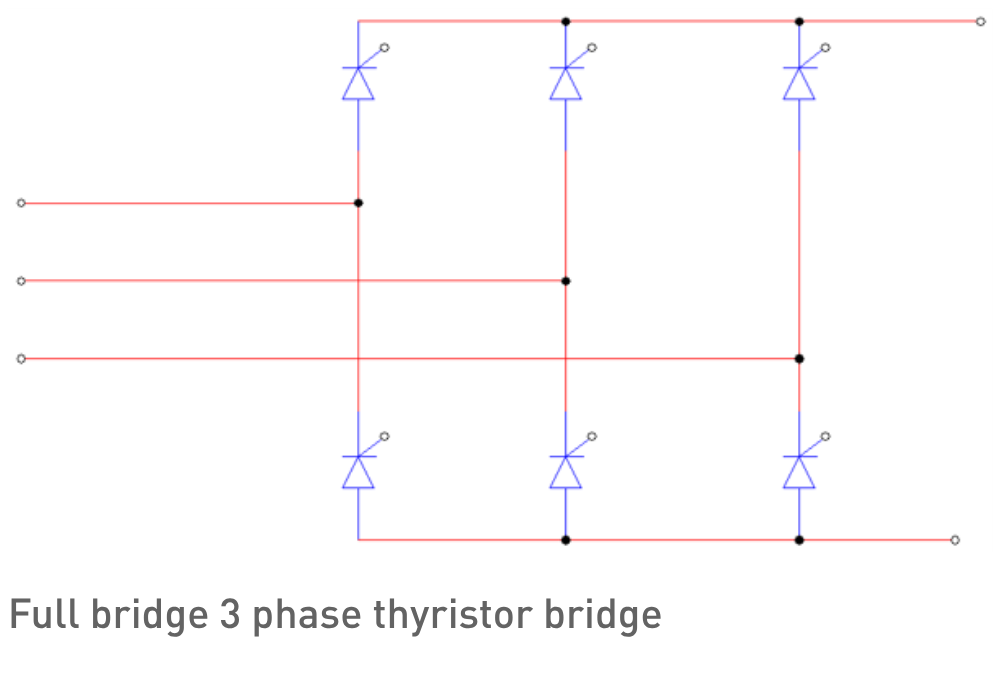
In the past, many thyristor-based power supplies were developed. The advantages are:

  • Low cost
  • Robust
  • Small volume But these power supplies produce a lot of voltage and current harmonics on the input mains Example: Let’s take an annealing process with lamps:
  • 480Vac, 3 phase net
  • The power supply should make 200Vdc, 170kW of power

A simulation is run to see the effect of the cable length.

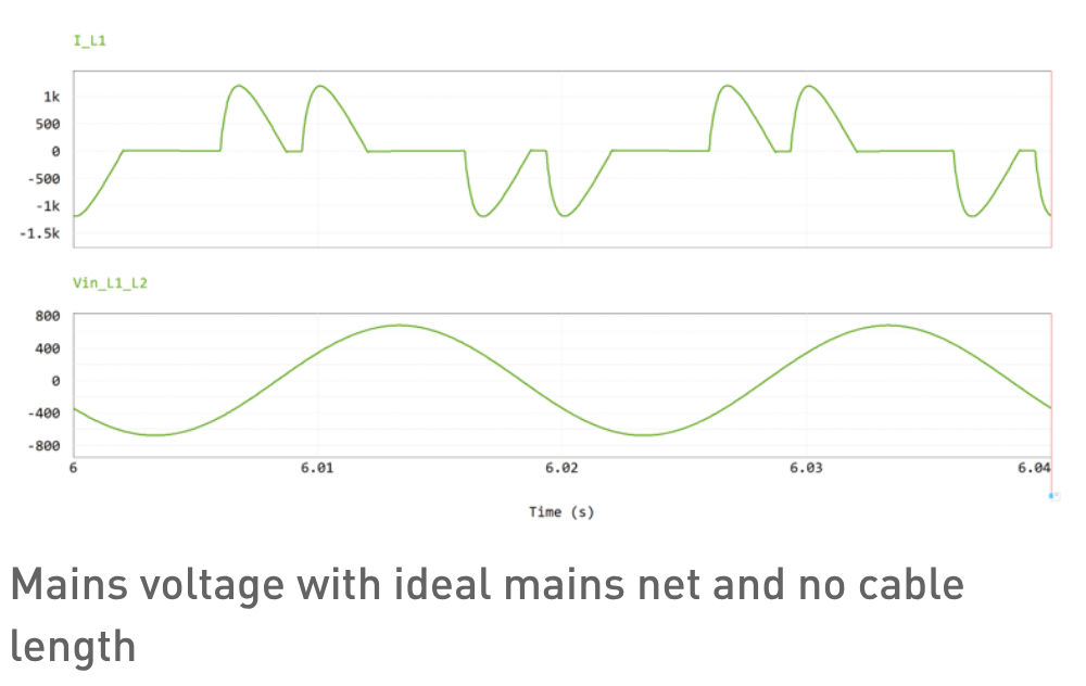
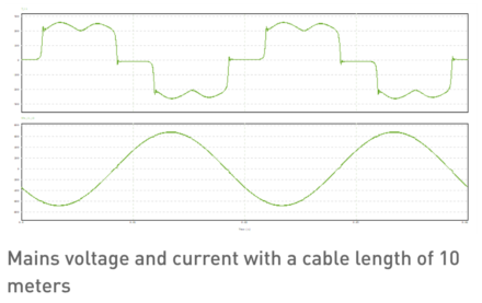
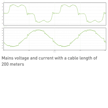
The voltage is still a perfect sine wave (since the mains net is ideal), but there are a lot of current harmonics.

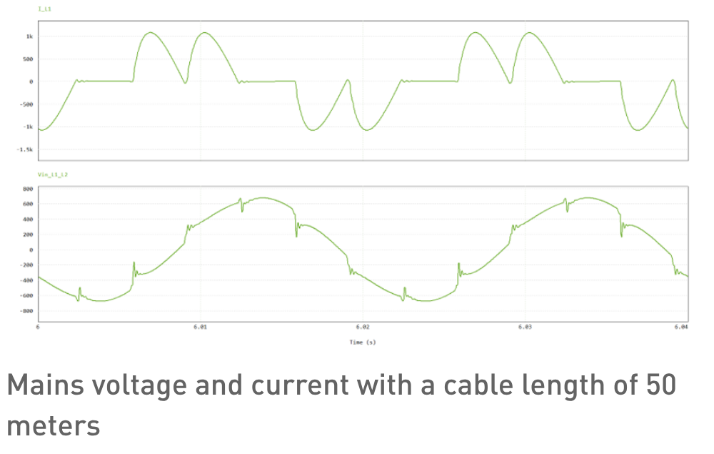
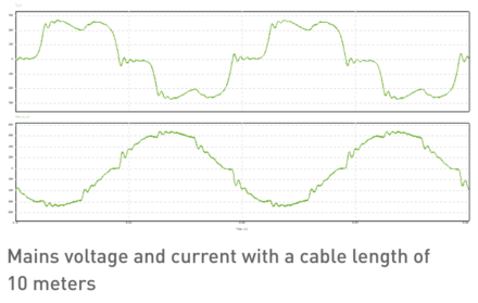
If the cable length is increased to 50 meters, already the voltage distortion is clearly visible.

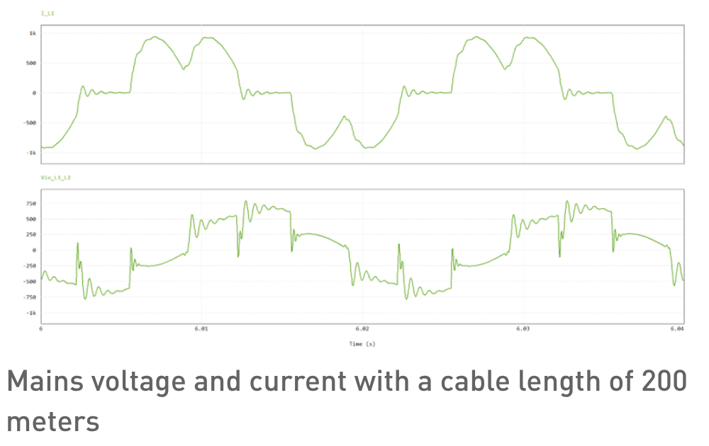
If the cable length is 200 meter the voltage distortion is over 33%, so far beyond the allowed 8%

In the following table, the voltage harmonic distortion is given as function of the cable length.

Cable length

Input current (Arms)

THDv

THDi

609

0%

78%

20

609

5%

71%

40

610

9%

64%

60

610

13%

58%

80

610

16%

53%

100

610

20%

49%

120

610

28%

46%

140

610

29%

43%

160

610

31%

41%

180

609

34%

39%

200

609

38%

37%

220

609

38%

36%

240

608

40%

35%

260

607

41%

34%

280

606

43%

33%

300

606

45%

32%

At 40 meters, the THDv (total voltage harmonics) is already over the limit. The THDi (total current harmonics) decreases with the cable length, this is due to the cable inductance. The cable inductance “filters” the higher current harmonics.

Note that the input current is very high. Ideally, if the power supply would not produce any harmonics and the efficiency is 100%, the input current would be $$ I_{\mathrm{rms}} = \frac{P_{\mathrm{out}}}{V_{\mathrm{in}} \cdot \sqrt{3}} = \frac{170000}{480 \cdot \sqrt{3}} = 204\,\mathrm{A_{rms}} $$ With the thyristor solution, the input current is 3x higher, resulting is a thick input mains cable.

Line reactors

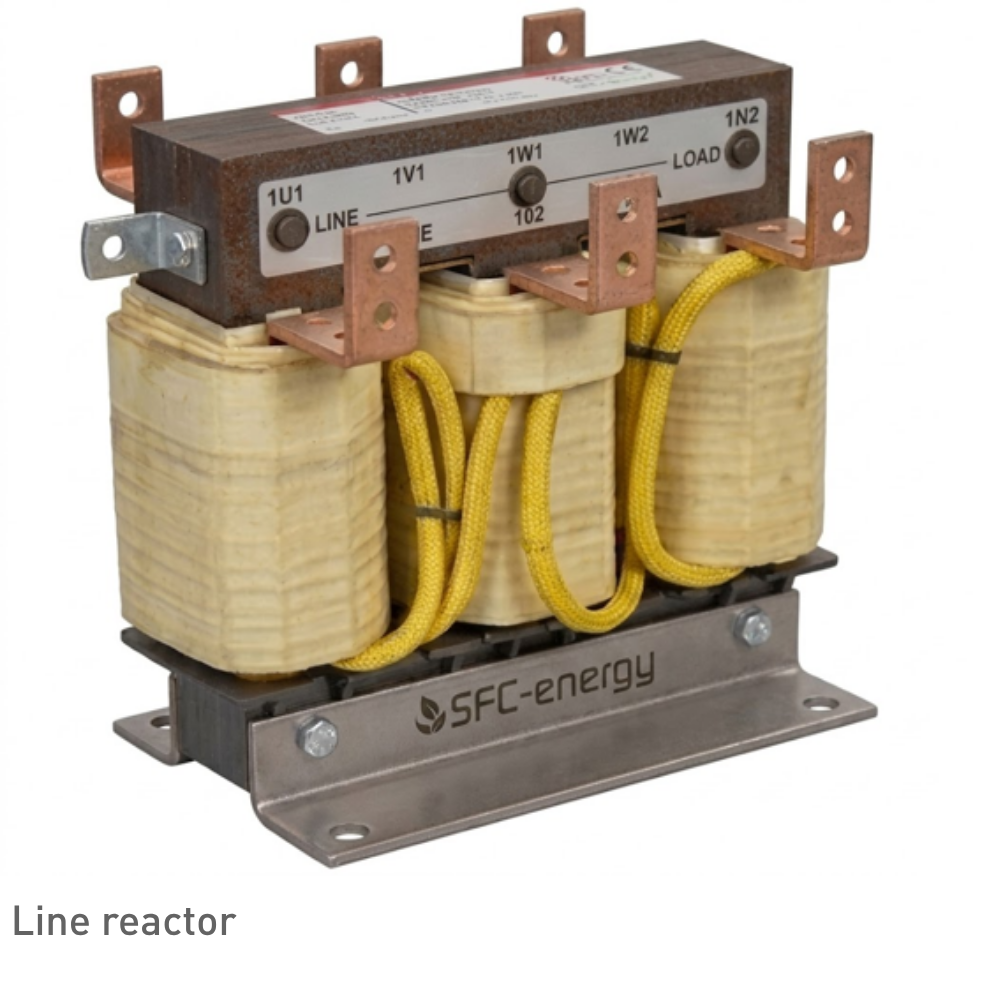
To overcome this harmonic distortion problem with a thyristor-based solution, a line reactor (3 phase coil) can be placed to reduce the voltage harmonics.

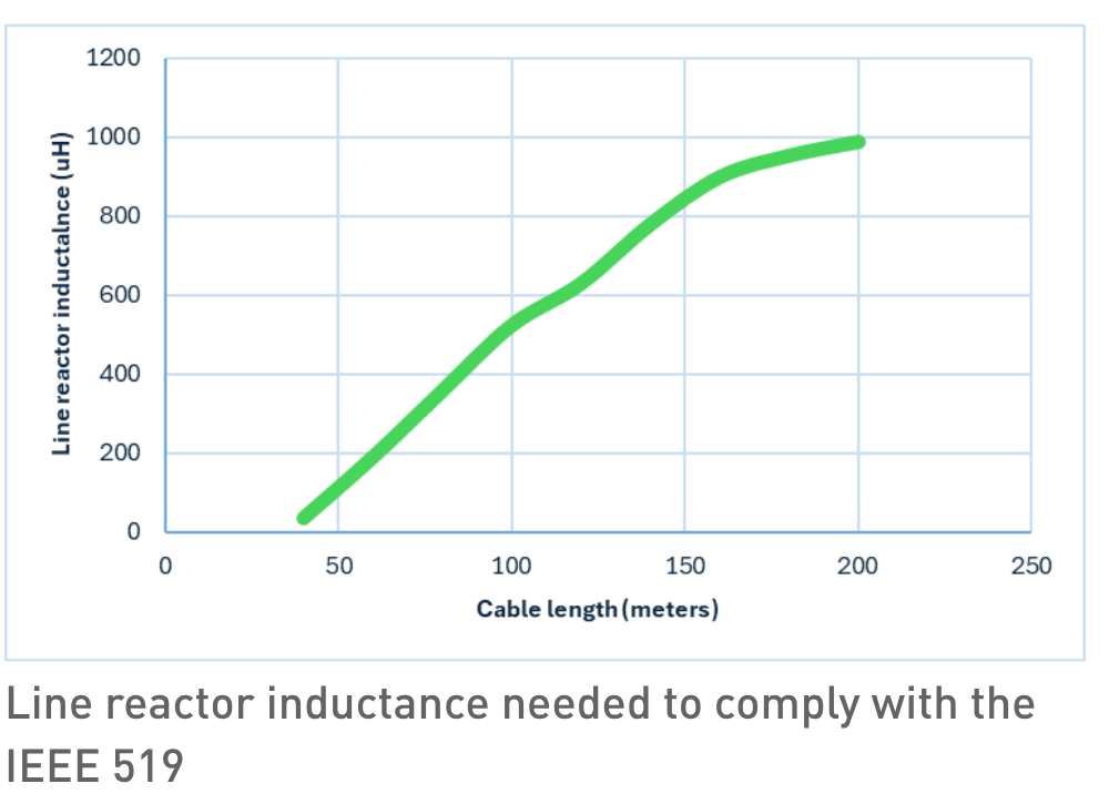
The inductance of the line reactor depends on the cable length and required power. The graph below shows the required line reactor as function of the cable length using the same example of a load of 200V, 170kW. Especially at high currents, and high inductance these line reactors become bulky and heavy. Advantage is that the power factor improves a lot, and the input current drops from 610Arms to 485Arms, reducing the mains cable thickness needed for this unit .

The inductance of the line reactor depends on the cable length and required power. The graph below shows the required line reactor as function of the cable length using the same example of a load of 200V, 150kW. Especially at high currents, and high inductance these line reactors become bulky and heavy. Advantage is that the power factor improves a lot, and the input current drops from 610Arms to 485Arms, reducing the mains cable thickness needed for this unit .

Single stage DCDC with diode rectifier

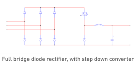
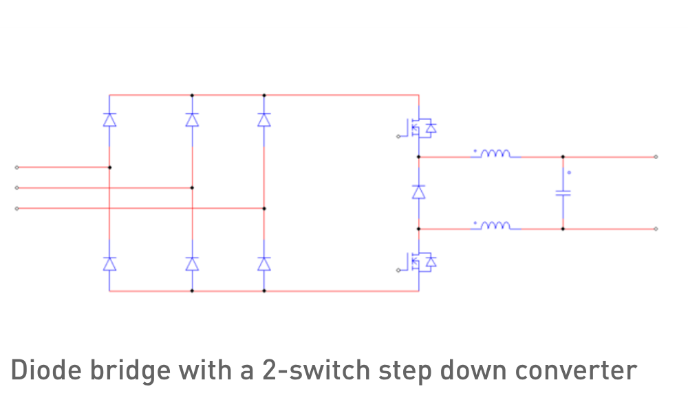
Improvements can be achieved by using a full bridge diode rectifier, with a buck (step down) converter.

Although there is clearly voltage distortion, it is far less than with a tyristor controlled bridge

L

Irms

THDv

THDi

20

263

3,7%

26,3%

40

243

3,5%

26,0%

60

244

4,2%

25,4%

80

245

4,8%

25,3%

100

246

5,3%

24,8%

120

246

5,8%

25,0%

140

247

6,3%

25,0%

160

248

6,8%

24,0%

180

248

7,4%

24,3%

200

249

7,8%

23,9%

At 200 meter cable length, the THDv is just under the limit of 8%

Paschen's Law

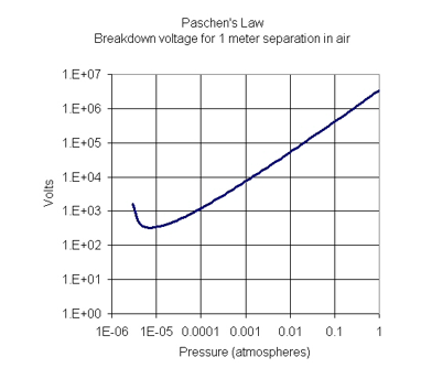
In the above example, an output voltage of 200V for the annealing process is used. In a low pressure environment, the breakdown voltage can be much lower than in normal atmospheric environments

With a thyristor based or diode bridge with DCDC converter bases topology, the output minus towards earth, is equal to the rectified minus voltage behind the diode bridge. At 480Vac mains input, this means that the maximal voltage on the minus pole is (-480/√3) * √2 = -391V. Ideally the maximal voltage towards PE is balanced and therefore minimized.

2 switch Step down converter

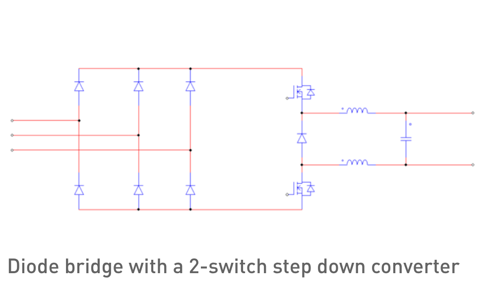
A 2-switch step down (Buck) converter can be used to balance the output voltage. It basically does 2 things:

  • It regulates the output voltage to the desired output voltage
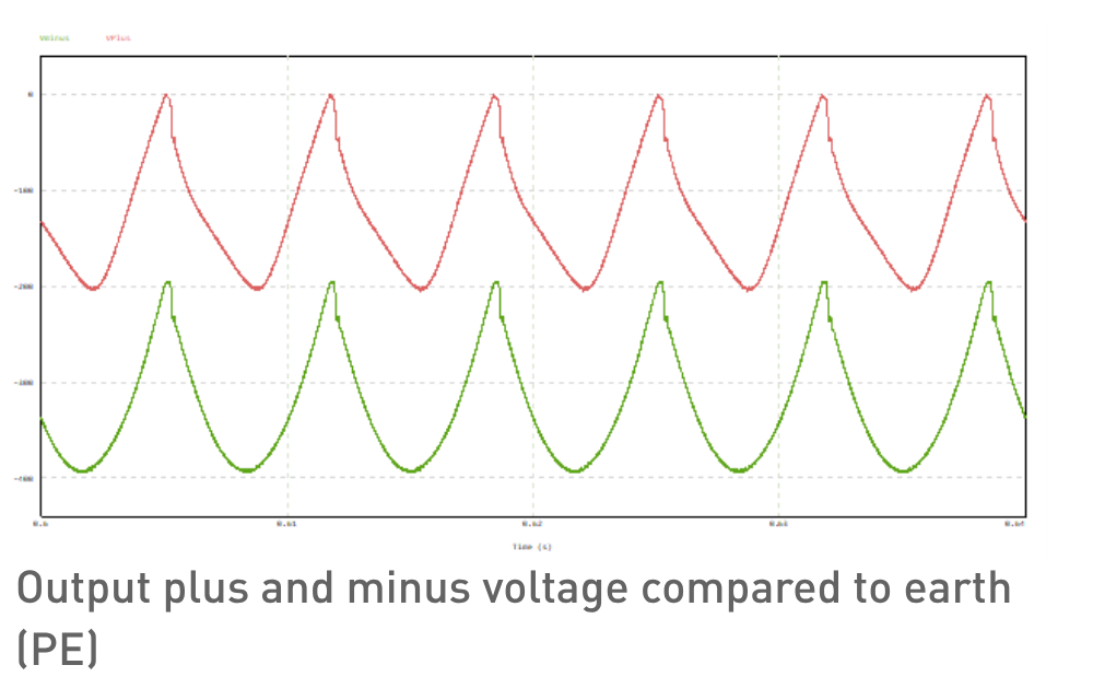
  • It balances the output voltage around PE

The control loop need to quickly balance the output around earth, but also must regulate the output power. The input mains frequency is either 50 or 60Hz, giving a rectified mains frequency of 300 or 360Hz. To keep the output voltage balances around PE, a quit aggressive control loop is required to compensate for the large input voltage swing. This more aggressive control loop together with a long cable and its equivalent cable impedance is a combination that does not go well together.

So, although this topology will the solve the breakdown voltage to earth, it introduces a lot of harmonics and a very complex control strategy considering the cable length can vary a lot.

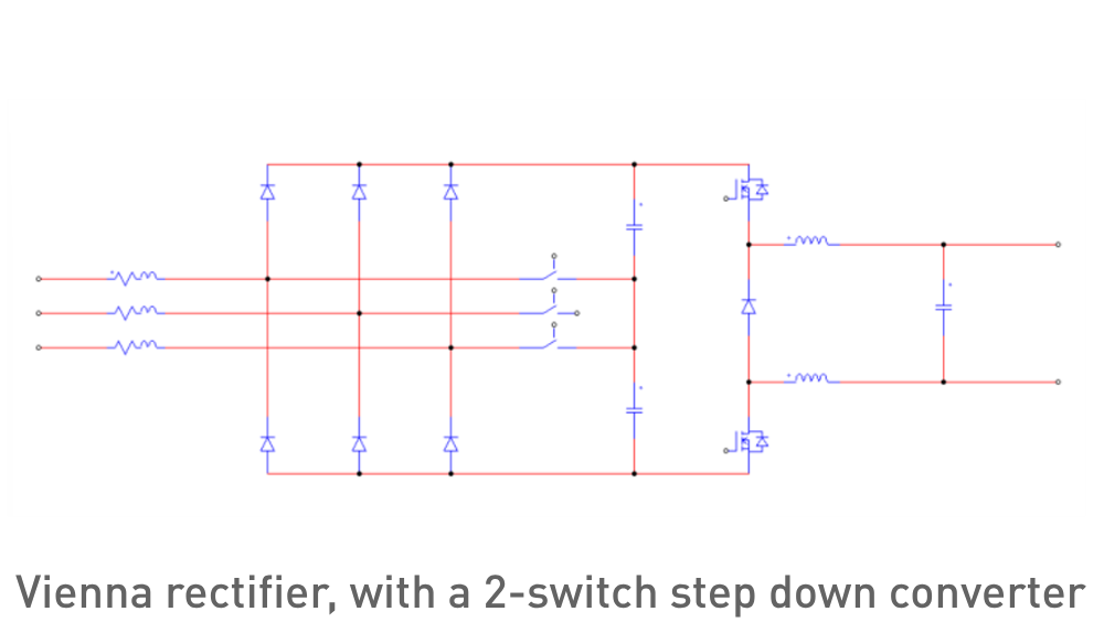
Viena rectifier, with a 2-switch step down converter

To solve all the above issues: Harmonics and balancing the output voltage around earth, a 2-stage converter is required. Stage 1: e.g. a Vienna rectifier. This stage rectifies and boosts the input voltage to a stable DC output voltage balanced around earth. Also, the input current will have hardly any current harmonics and therefor hardly produces any voltage harmonics Stage 2: A 2-switch buck (step down) converter to make a balanced output voltage around earth.*

The disadvantage is the cost and the volume. Since this converter has 2 stages, it is obvious that those 2 parameters increase.

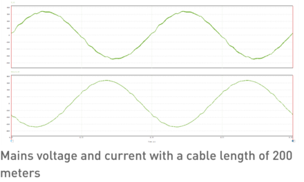
Bus seeing the waveforms below, the advantaged are clear:

In the former figures, it shows that the mains harmonics is very low, while the output voltage is nicely balanced around earth. The table below, shows that the THDv is well within limits.

L

Irms

THDv

THDi

20

272

0,2%

1,2%

40

272

0,3%

1,4%

60

272

0,5%

1,5%

80

272

0,6%

1,6%

100

272

0,8%

1,7%

120

272

0,9%

1,8%

140

272

1,1%

1,9%

160

272

1,3%

2,1%

180

272

1,4%

2,2%

200

272

1,6%

2,3%

Conclusions

If multiple devices share one Point of Common Coupling, it is important to reduce the current harmonics produced by the power supply, to comply with the IEEE 519. Different techniques can be used to lower the harmonics. The required topology can differ for each use case.

Q&A

Is a Vienna rectifier and a 2-switch step down converter always required

It really depends on the requirements. The Vienna rectifier with a 2-swicth can be a very good solution for some applications, like annealing with high power. For low power applications, applications with a completely different output voltage range or when galvanic isolation is required, other topologies might be better.

Also, if there are no other users on the same mains net, or the cables lengths are short, a simpler topology can be used

Is the IEEE 519 mandatory

No, IEEE 519 is not mandatory by itself — it's a recommended practice, not a legal standard. However, there are situations where it becomes binding in practice:

When IEEE 519 does become mandatory/binding:

  1. Contractual requirement – If a customer, utility, or purchase specification requires IEEE 519 compliance, it becomes binding for that specific project.
  2. Utility requirements – Some utilities (especially in the US) incorporate IEEE 519 limits into their interconnection agreements. If you want to connect to (or stay connected to) the grid, you then must comply.
  3. Referenced by other standards/regulations – If a local law, building code, or another (mandatory) standard references IEEE 519, it becomes indirectly mandatory.
  4. Certification/tender requirements – In government tenders or certain certifications, compliance can be set as a requirement.

Are there other topologies to lower harmonics

Yes there are multiple e.g.

  • Three-phase 6-switches, Boost-type Active PFC
  • Swiss Rectifier
  • Multilevel Neutral Point Clamped (NPC) Active Rectifiers
  • Modular Multilevel Converter (MMC) based rectifiers

Are there other topologies to balance the output around earth

Yes many, the easiest way is to use an isolated DC/DC converter with a midpoint. It gives you a prefect balancing performance, but it comes with a price: Lower efficiency, less compact, higher price.

Are there other things to consider besides harmonics and grid stability when choosing a power supply

Yes many. Below some are listed, but there can be many more

  • Input voltage range
  • Ripple and noise
  • Transient (dynamic) response
  • Rise and fall times
  • EMC
  • Safety (product and human safety)
  • Environmental conditions
  • Size
  • Weight
  • IP class
  • Shock and vibration
  • Lifetime and MTBF
  • Interfacing and diagnostics
  • Etc. etc.

So, choosing the right power supply is not an easy task and is often underestimated. It mostly required the expertise of the power supply expert and a good knowledge about the end application.