
Minimizing Electron Beam Distortion by Scanning Coil

Key Technical Insights

  • Scan distortion is one of the main accuracy limits in electron beam systems.
  • A saddle coil pair is the best option for low parasitic fields and manufacturability.
  • Controlled precision manufacturing of each coil and each coil assembly is critical to limit distortion


Open PDF Version

Introduction

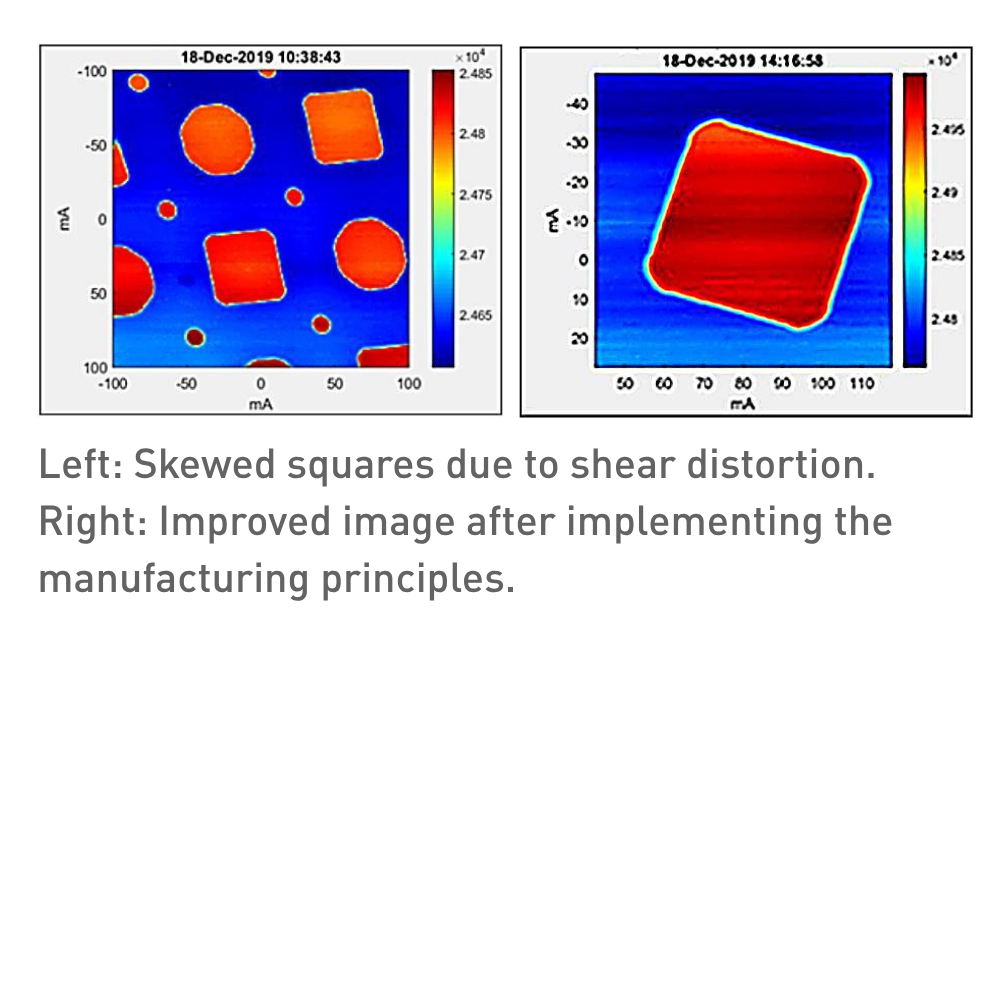
Distortion is a classic problem in scanning-coil systems, and it is a different issue from resolution-limiting aberrations like coma or astigmatism. In SEM, STEM, and e-beam lithography, scan distortion is one of the main accuracy limits, even when resolution is excellent.

Scanning Basics

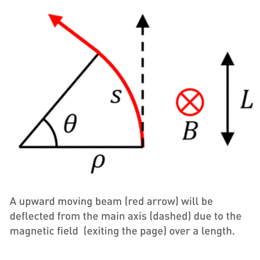
In a particle beam, the measure of the resistance of the beam to deflection by magnetic fields is expressed as the rigidity Bρ (units of Tesla.meter). If the beam is subject to a uniform perpendicular magnetic field B, the Lorentz force will create a circular motion. The bending radius becomes r = Bρ/B. After travelling a length s, the angular deflection is

$$ \theta \approx \tan\theta = \frac{L}{r} = \frac{BL}{B\rho} $$

This magnetic field is typically created by a saddle coil pair of length L along the beam direction.

Saddle Coil Pairs

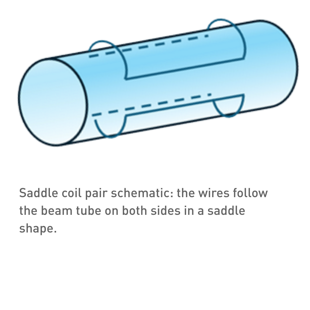
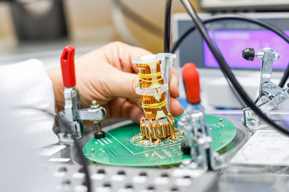
A saddle coil consists of wires running along the beam tube, and then curved around the tube on both ends. The resulting geometry looks like a saddle. To create a perpendicular, almost uniform field another coil should be placed symmetrically on the other side of the beam, creating a saddle coil pair. Each pair can only scan in one direction, so two pairs are common for an xy-scanning application.

A single coil with the same angular wiring as two saddle coils, is possible by winding the wires around the beam. However, this is seldom used since a saddle coil pair can easily be produced and mounted onto the beam tube. Secondly, their symmetric angular wire leads to better cancellation of parasitic fields, leading to a cleaner uniform field.

Distortion

Real scan coils do not create a perfect magnetic field, but with careful design and manufacturing distortion can be limited to acceptable limits. A quick overview of the design rules and manufacturability aspects are given here.

For the individual coil
  • Precision winding on CNC winding machines, allowing high coil winding speeds and minimal wire stresses.
  • Orthocyclic winding making sure the windings are at defined positions, and minimize air gaps.
  • Crossovers only in the angular legs. Crossover positions are programmable on the CNC winding machine.
  • Controlled wire tension and braking force during winding ensuring stable wire positioning and preventing relaxation of the copper wire.
  • Precision bending of the coil into the saddle shape, while maintaining the orthocyclic structure.
  • Focus on process reproducibility, such that performance is identical product-to-product and batch-to-batch.
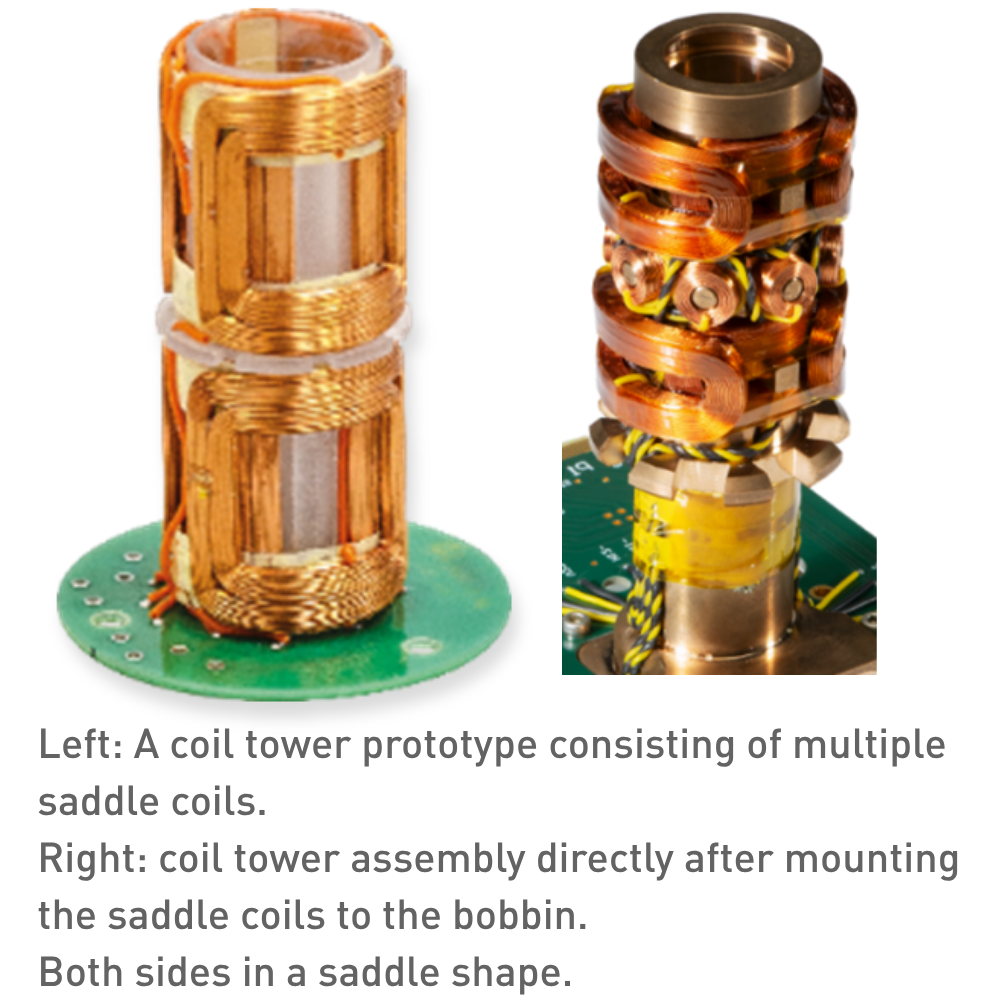
For the coil assembly
  • Concentric alignment of the pair such that the magnetic field is as uniform as possible.
  • Precision alignment of the pairs to minimizing crosstalk between the pairs and place them in the same magnetic center.
  • Keep the coil in place and protect from environment: epoxy cast the entire coil assembly
  • Magnetic and electrical shielding of the entire assembly

Q&A

What are the primary causes of scan distortion in saddle-coil scanning systems?

Non-uniform winding geometry, misaligned coil pairs, air gaps from inconsistent orthocyclic winding, uneven wire tension or relaxation, and asymmetric crossover placement produce parasitic fields and non-uniform B leading to distortion.

How much can manufacturing control reduce distortion, and which tolerances matter most?

Tight, repeatable control can reduce distortion from noticeable to sub-resolution levels; the most critical tolerances are axial concentricity of the pair, angular position of windings (orthocyclic precision), crossover location repeatability, and consistent saddle-bend geometry—target micron-level positional repeatability and sub-degree angular repeatability where feasible.

Why do saddle coil pairs outperform single wrapped coils for minimizing parasitic fields?

Symmetric saddle coil pairs cancel opposing angular lead fields and isolate the central uniform perpendicular field; this symmetry reduces net parasitic multipoles and crosstalk compared with single wrapped geometries that have asymmetric return paths.

What verification and protection steps should be used after assembly to ensure low distortion in the field?

Perform magnetic field mapping (two-axis scans and multipole decomposition) to quantify distortion, verify concentric alignment with mechanical metrology, pot/epoxy the assembly for mechanical stability, and add magnetic/electrical shielding; re-test after potting and thermal cycling to confirm stability.

Discover our custom-designed coil assemblies

We partner with our customers to engineer and manufacture high-quality coils assemblies. Through close collaboration, we tailor each solution to meet exact application requirements—ensuring reliability, performance, and seamless integration into advanced systems.

More information

Contact our expert Stefan Slot

Get expert advice on custom coil assemblies tailored to your application.