Aberration Correctors Spherical Aberration Correctors in Electron Microscopy

Key Technical Insights

  • Aberration is the limiting effect in electron microscopy
  • Correction requires multiple higher-order multipole lenses.
  • Manufacturing these correctors demands µm/µrad mechanical alignment, orthocyclic CNC coil winding, and full encapsulation.
  • Even with perfect mechanics, sub-ppm power supply stability and vibration isolation are required.


Open PDF Version

Introduction

Aberration is the limiting effect in electron microscopy, as opposed to diffraction limited commonly the case in light optics. Electron optics are aberration-limited because even small deviations of electron trajectories cause spherical blurring, which dominates over diffraction at the pm scale in practical lenses.

Spherical Aberration

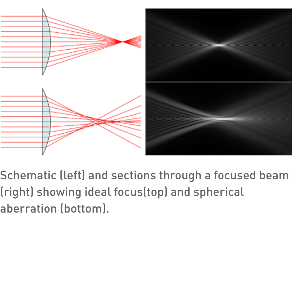
A perfectly rotationally symmetric lens does not produce a perfect homogeneous field. The focusing strength varies with off-axis distance due to the lens geometry, such that higher-order aberrations grow rapidly. For a small ray angle θ, an ideal lens would focus an image at a radius $$ \Delta r_{image} = f\theta $$ where f is the lens focal length. For a real lens, the focal length is approximated by $$ \frac{1}{f_{\mathrm{eff}}} = \frac{1}{f}\left(1 + C_s \theta_0^2 + \cdots\right) $$

Where $$ C_s $$ is the spherical aberration coefficient. Hence the aberration-induced blur is $$ \Delta r_{C,s} \approx C_s \theta^3 $$ For a practical system with θ=10 mrad and C_s=1 mm this already gives $$ \Delta r_{C,s} \approx 1 $$nm Compared to the electron wavelength (e.g. 2.5 pm at 200 kV) and the desired resolution this is a huge (400x) difference. For comparison, this is reversed for a typical visible-light microscope, e.g. diffraction limited at 200 nm (high-NA oil immersion objective (NA ≈ 1.4) at green light (λ ≈ 550 nm)) with a smaller aberration blur in well-corrected lenses.

Multiple Stacking

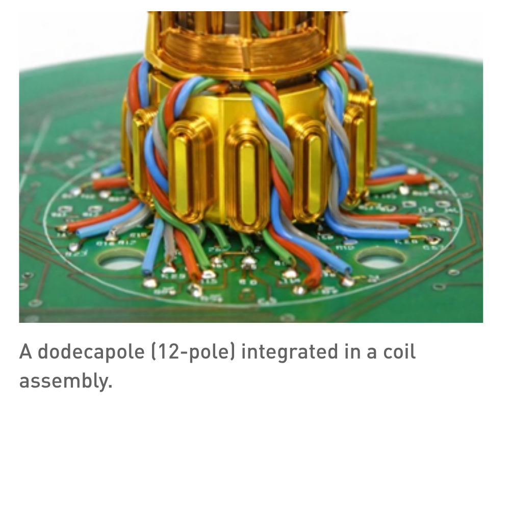
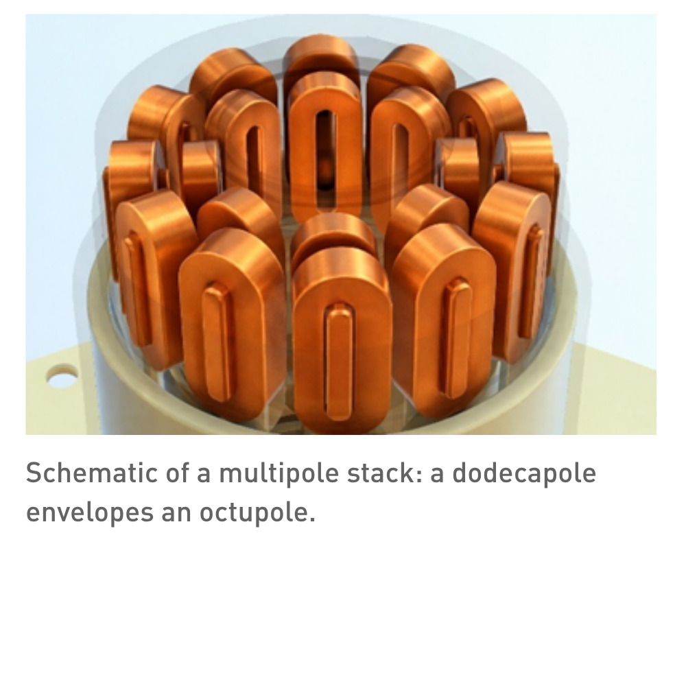
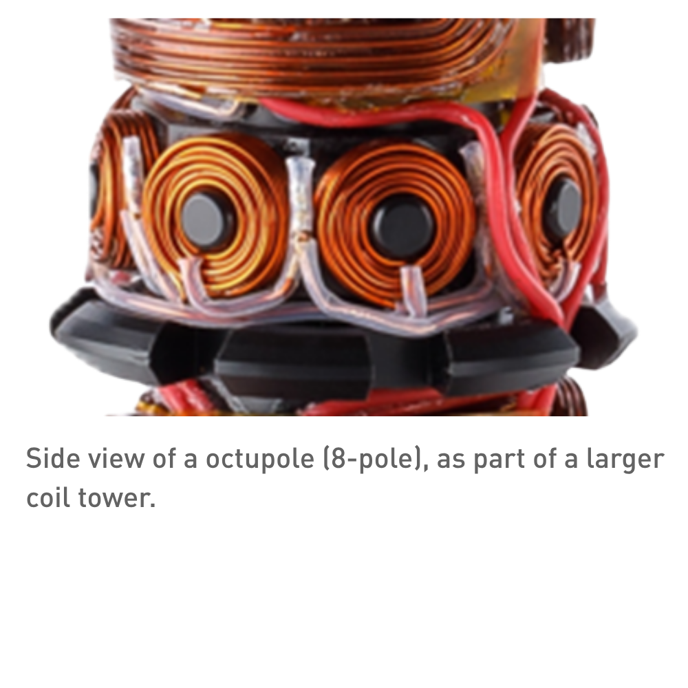
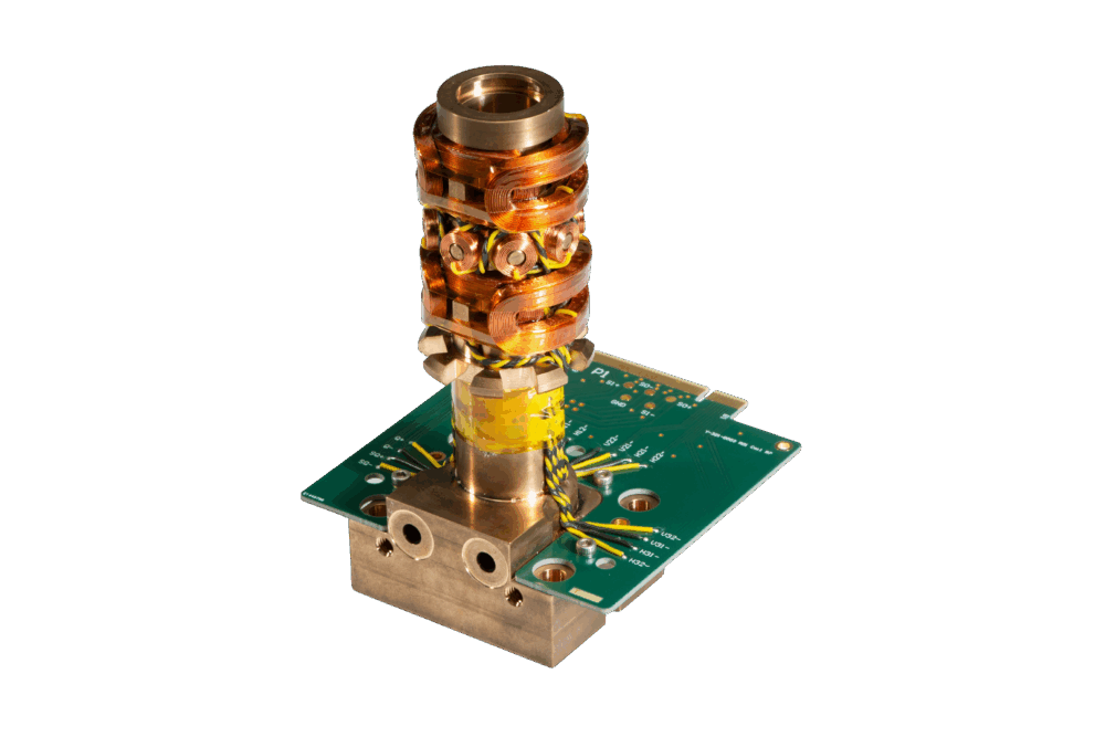
Near the axis, the transverse magnetic field can be expanded as a power series, where each term is known as a multipole. Spherical aberration is usually corrected by higher orders, such as octupole (8 poles) or dodecapole (12-poles). A decapole (10 poles), does nest cleanly in lower-order corrections, makes it too sensitive to alignment, whereas a combined octupole and dodecapole gives more degrees of freedom to correct the beam.

Downsides are increased complexity and stronger fields needed (more current, noise, heat, magnetic saturation, eddy currents, inductance). This demands µm/µrad-level magnetic axis alignment. Final alignment is electronic, requiring sub-ppm current stability, but dynamic aberration correction during operation won’t be able to correct if mechanical tolerances were worse.

Mechanical layout

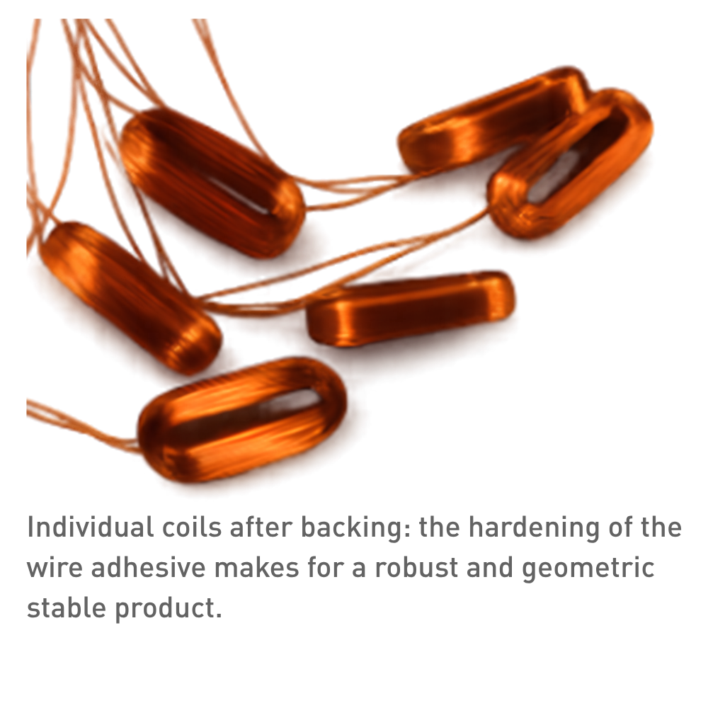
Individual self-supporting coils are generally preferred in this application. Self-bonding wire typically features a thermoplastic adhesive layer atop the electrical insulating layer, which reflows during a baking step. This design simplifies the manufacturing process by eliminating the need for fixation components, thereby saving volume, costs, and complex tolerance chains. Additionally, the coil remains reworkable and replaceable, and it exhibits greater dimensional stability even under high loads. Ferromagnetic yokes for field enhancement to limit current in outer multipole. Usually modern fittings and bonding processes are sufficient for the required tolerances.

Manufacturability

Real multipoles do not create a perfect magnetic field, but with careful design and manufacturing distortion can be limited to acceptable limits. A quick overview of the design rules and manufacturability aspects are given here.

For the individual coil
  • Precision winding on CNC winding machines, allowing high coil winding speeds and minimal wire stresses
  • Orthocyclic winding making sure the windings are at defined positions
  • Crossovers only in the axial legs. Crossover positions are programmable on the CNC winding machine
  • Controlled wire tension and braking force during winding ensuring stable wire positioning and preventing relaxation of the copper wire
  • Focus on process reproducibility, such that performance is identical product-to-product and batch-to-batch
For the coil assembly
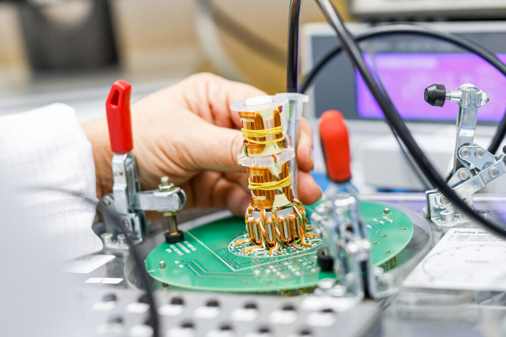
  • Concentric alignment of the pair such that the magnetic field is as uniform as possible
  • Precision alignment of the pairs to minimizing crosstalk between coils and align the coils in the same magnetic center
  • Local splicing by connecting stigmator coils locally instead of PCB connections to minimize parasites
  • Keep the coil in place and protect from environment: epoxy cast the entire coil assembly
  • Magnetic and electrical shielding of the entire assembly
  • Extremly stable power supplies: Below ~70 pm, even power supply noise becomes optical aberration and should be below ppm levels. And ideally water cooled to avoid mechanical noise

Q&A

Why can't you just use a better lens to fix spherical aberration in an electron microscope?

In light optics you can grind aspherical surfaces or cement doublets to cancel aberrations, but electron lenses are rotationally symmetric magnetic fields with no refractive surfaces to reshape. Scherzer's theorem (1936) proves that any static, rotationally symmetric electron lens free of space charge will always have positive spherical aberration. You have to break one of those symmetry conditions — which is exactly what multipole correctors do.

Why use octupole + dodecapole rather than just more octupoles?

An octupole alone can introduce the negative spherical aberration needed to cancel C_s, but it simultaneously introduces higher-order parasitic aberrations that it cannot independently control. Adding a dodecapole provides extra degrees of freedom to suppress those parasitic terms. A decapole (10-pole) would seem like a middle ground, but its lower symmetry makes it hypersensitive to alignment errors, so the octu + dodecapole combination is the practical sweet spot.

What happens if the mechanical alignment is off by more than the specified tolerances?

Electronic alignment (via trim coils and software) can compensate for small residual mechanical errors, but it has a limited correction range. If the mechanical tolerances are too loose, the electronic correction saturates — meaning you consume your electrical "budget" just compensating for misalignment, leaving insufficient headroom for actual aberration correction during operation. The corrector then cannot reach its designed resolution.

Why does power supply noise matter at the sub-ppm level?

The lens excitation current directly determines the focal length. Current fluctuations translate into focal length jitter, which appears as image blur. Below ~70 pm resolution, even parts-per-million current noise produces aberration contributions comparable to the target resolution. This is why corrector power supplies are often water-cooled — not for the coils themselves, but to eliminate fan vibration and thermal drift in the electronics.

Why epoxy-cast the entire coil assembly?

Epoxy potting serves three purposes: it locks coil windings in place so they cannot shift under magnetic forces or thermal cycling, it damps mechanical vibrations that would translate into field instability, and it seals the assembly against humidity and contaminants that could degrade insulation or cause electrical shorts over time. Without potting, even microscopic wire movement during operation would introduce time-varying field distortions that the correction system cannot track.

Discover our custom-designed coil assemblies

We partner with our customers to engineer and manufacture high-quality coils assemblies. Through close collaboration, we tailor each solution to meet exact application requirements—ensuring reliability, performance, and seamless integration into advanced systems.

More information


Contact our expert Stefan Slot

Get expert advice on custom coil assemblies tailored to your application.